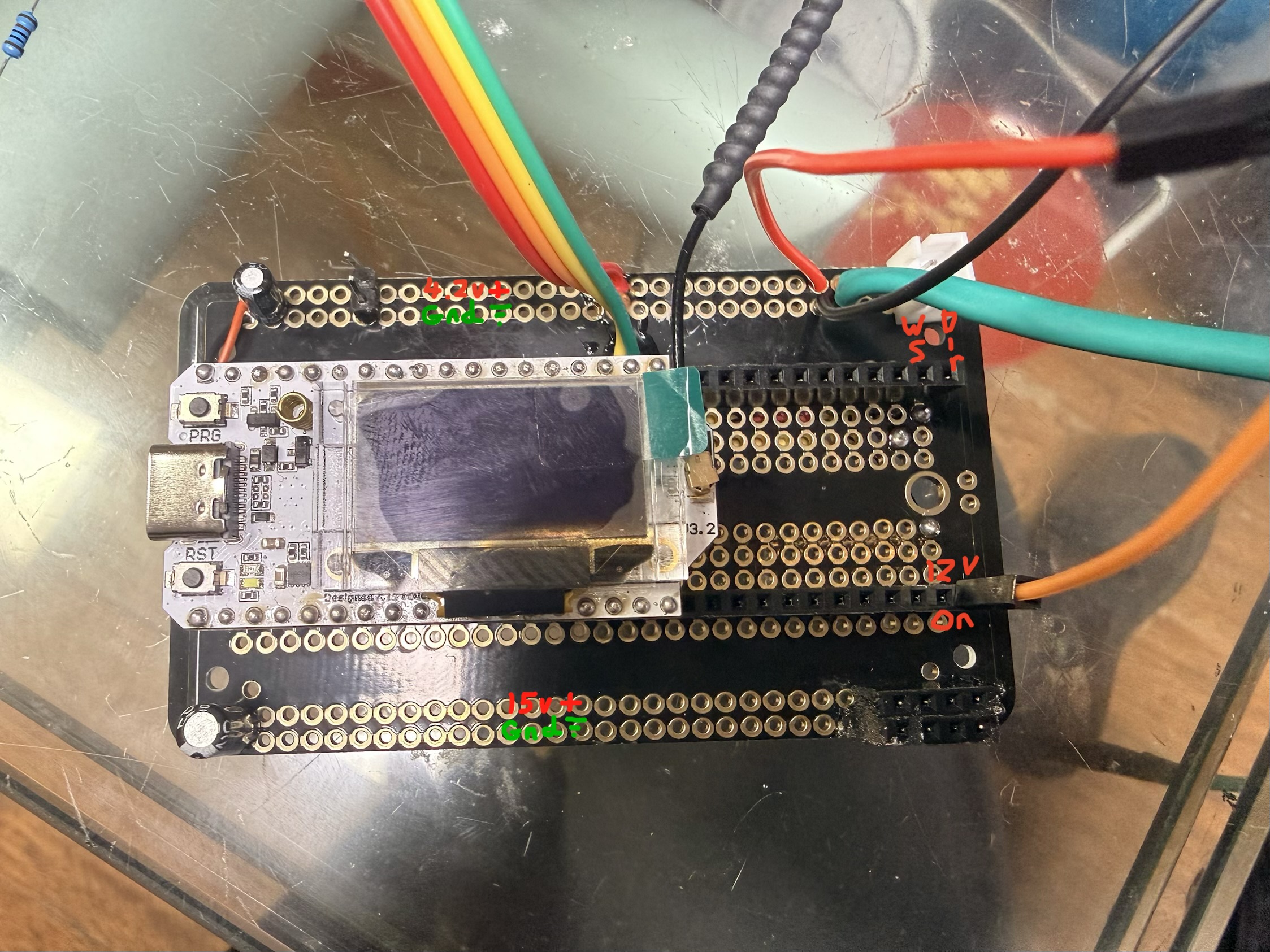
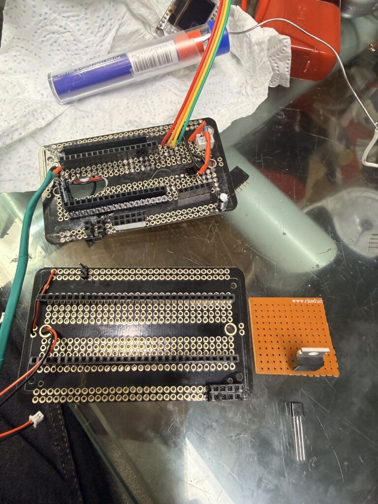
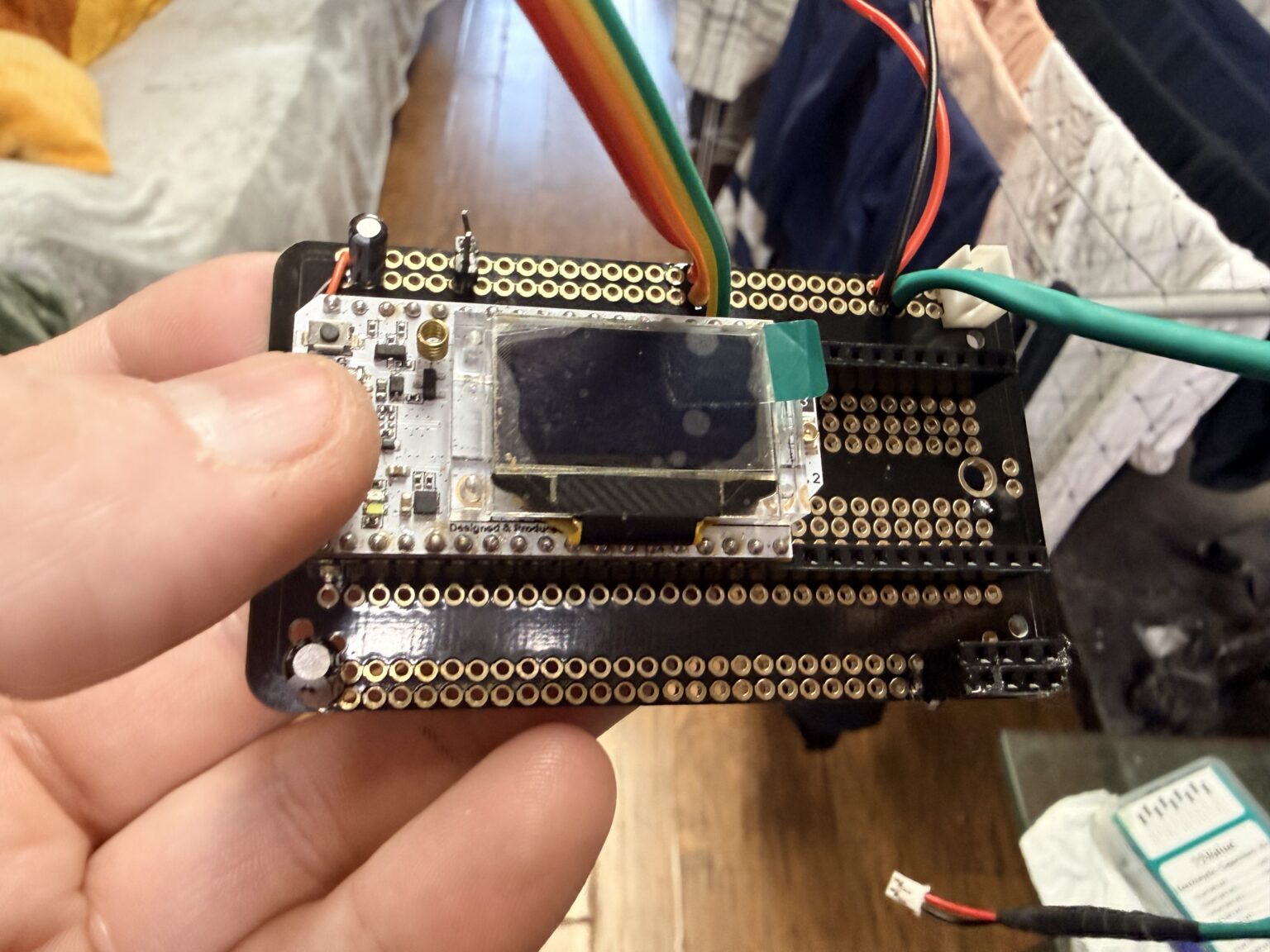
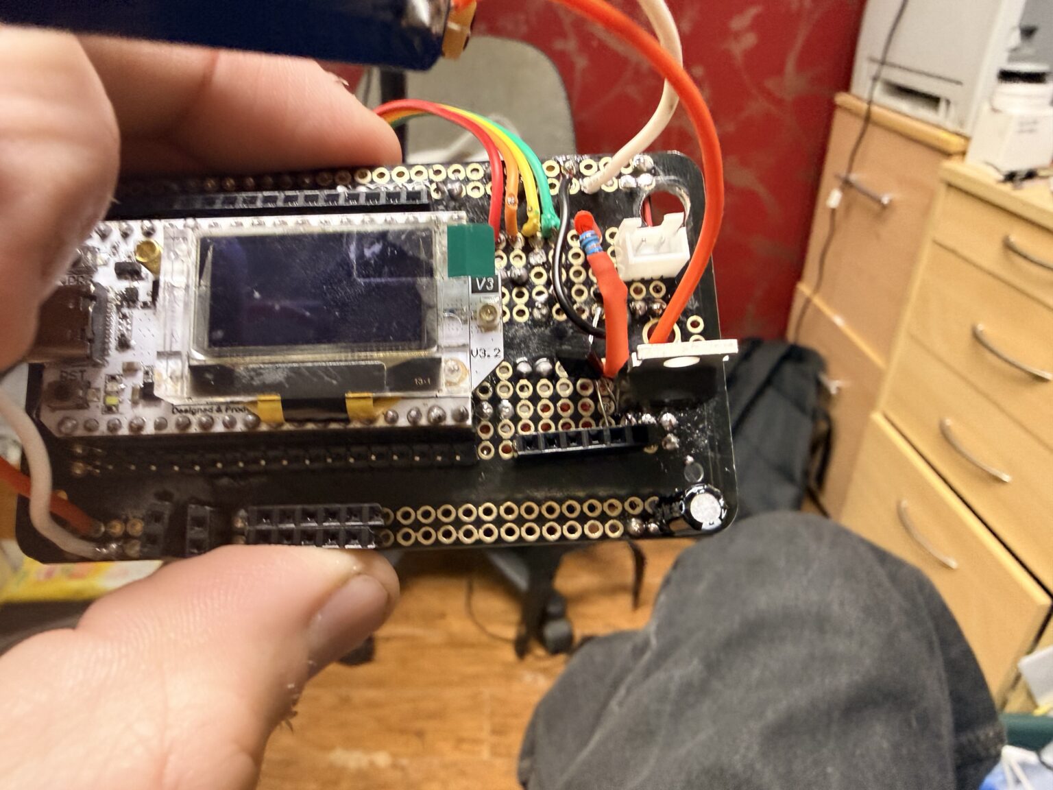
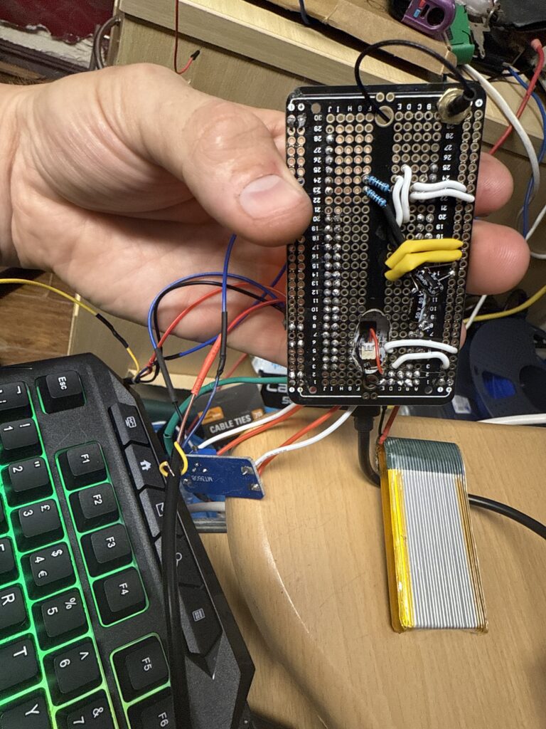
 The mainboard is pretty much complete
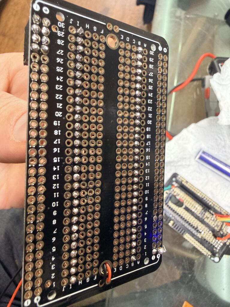
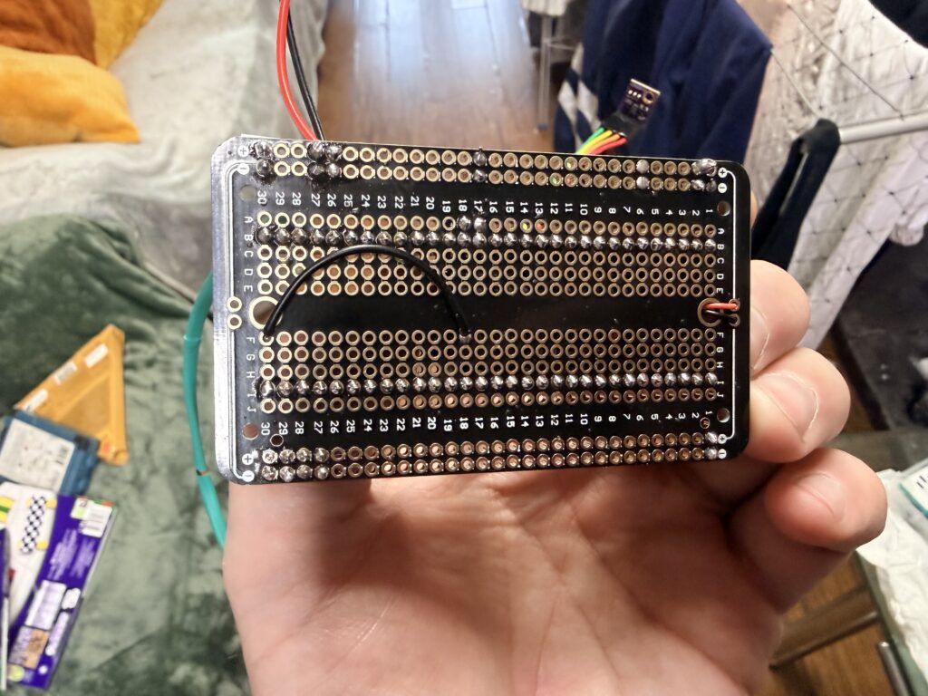
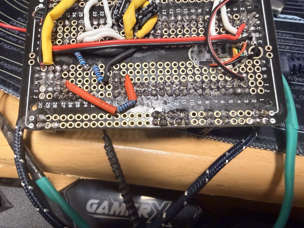
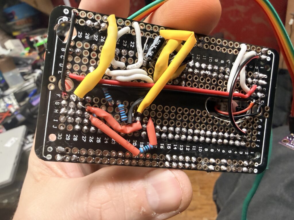
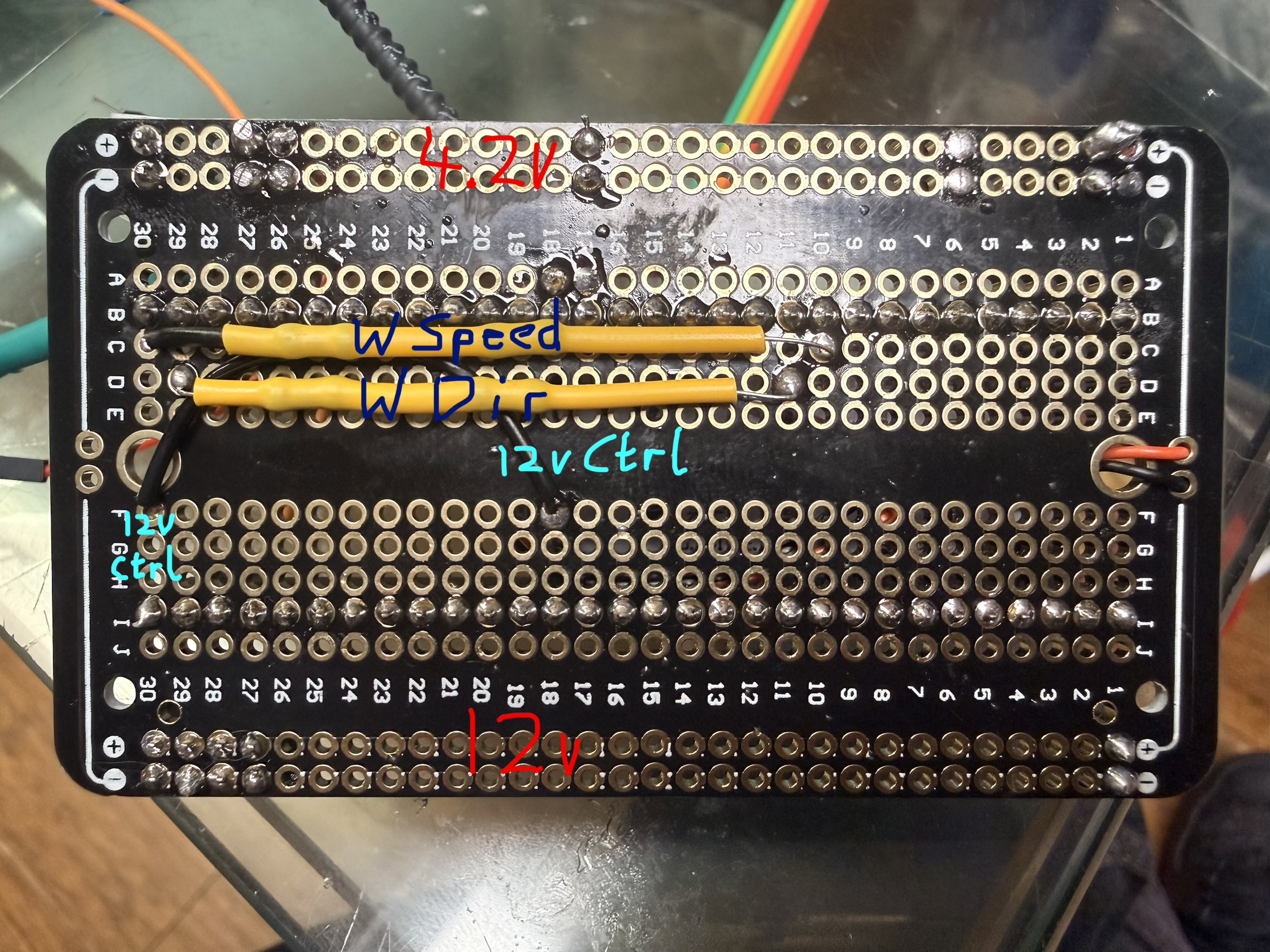 Back of the mainboard.
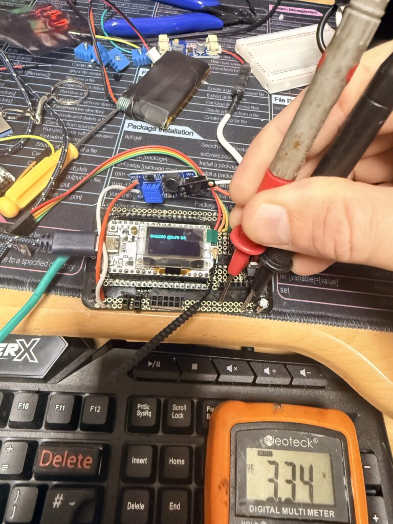
Now the next step is to plug it all in together and write a small C++ program to test the response on the DC-DC converter.
I’m hoping to mount the weather station at ///waggled.warms.clearing (What3Words) to give an excellent indication of conditions actually on the airstrip itself Runway 01/19; just to the side.
I have a GoFundMe set up; hopefully to raise enough money to buy all the sensors, batteries and solar panels I will need to make the project work and to commission it so everyone in the area can have access to its data. Chirk Airfield Weather Station Fund. Otherwise if I don’t get any help I’ll have to build it very slowly; piece by piece as I can afford to. Big “Thankyou!” to Al and Stuart for kicking off the fundraiser!
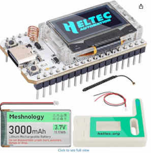
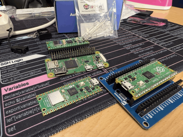
This is the Heltec ESP32 LoRa V3. I was originally aiming to use a Raspberry Pi Pico 2W but that would have meant spending quite a bit more money on a LoRa Hat to add to the Pico whereas this Heltec board came with LoRa, OLED display, WiFi and Bluetooth onboard all for just £33 off Amazon and has a dual core 200MHz ESP32 processor… all in a tiny 5cm x 2.5cm x 1cm wide board. It also came with a 3AH LiPo battery and it has an on-board charge controller so the board will just continue working for hours when the power fails from wind or solar. Exactly what we need as the Pi Pico doesn’t have any sort of battery interface.
Current draw at 3.3V is just 10 microAmps during deep sleep and around 150mA when using Bluetooth – not that we will be using Bluetooth; just the LoRa transceiver. All in all if we use a small wind turbine and/or solar panel with a battery we should never even come close to having any power supply problems.
Project Blog: Latest at the top: Please start from the bottom of the page unless you’re nearly up to date
The mainboard is pretty much complete
Back of the mainboard.
Now the next step is to plug it all in together and write a small C++ program to test the response on the DC-DC converter.
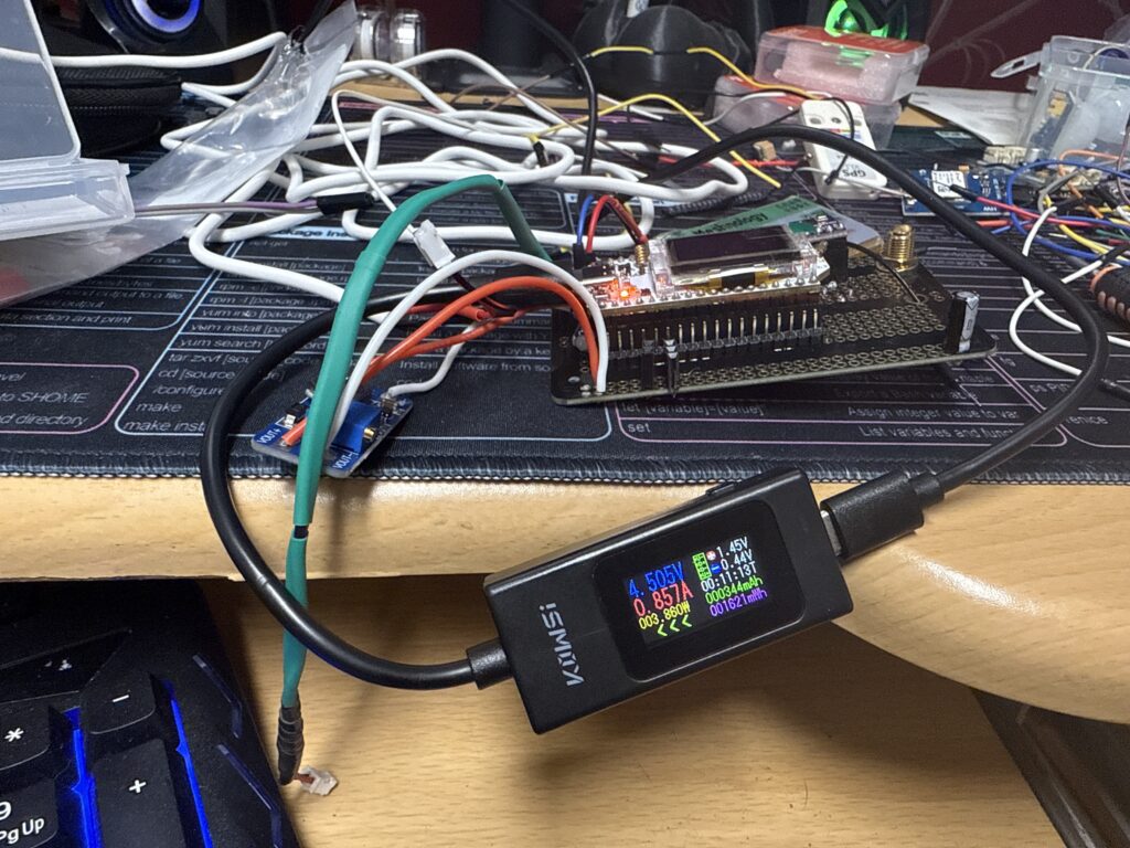
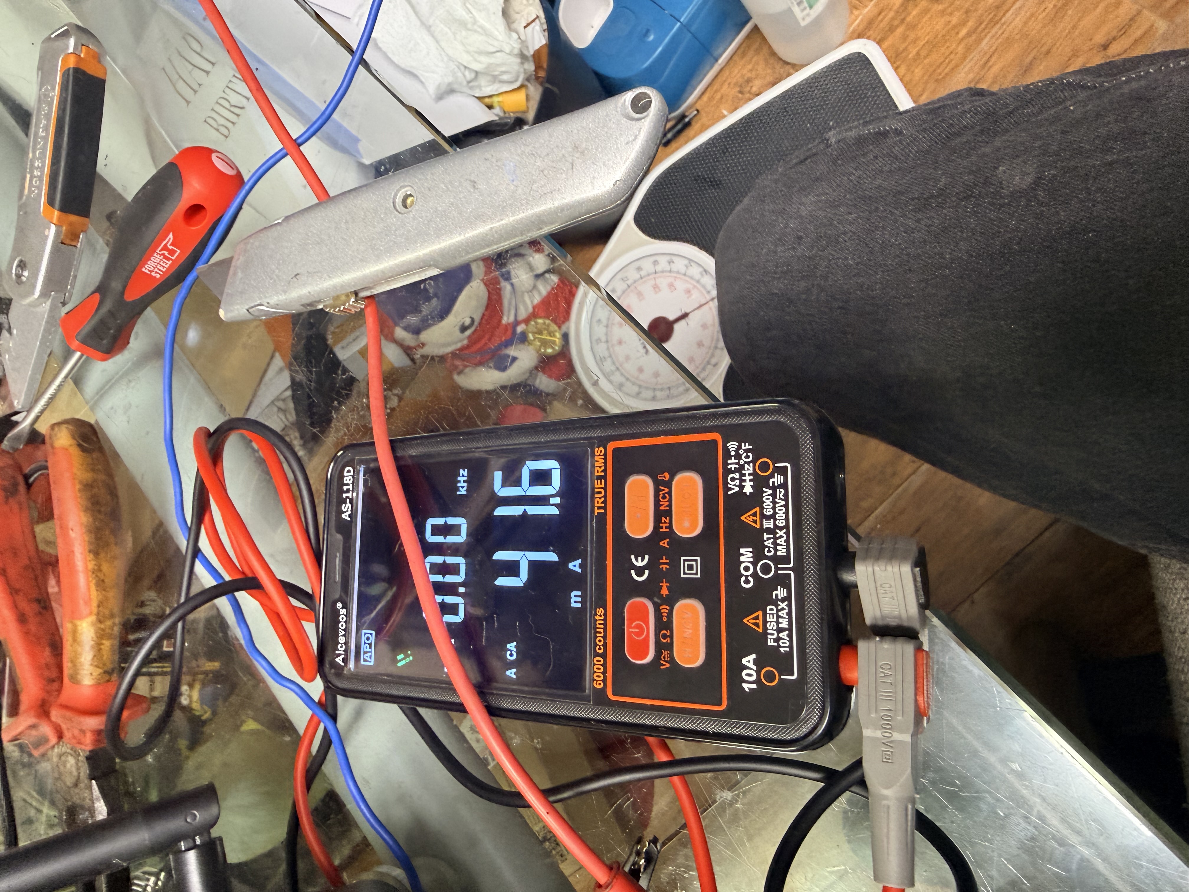 On activation the DC/DC converter draws around 40-50mA.
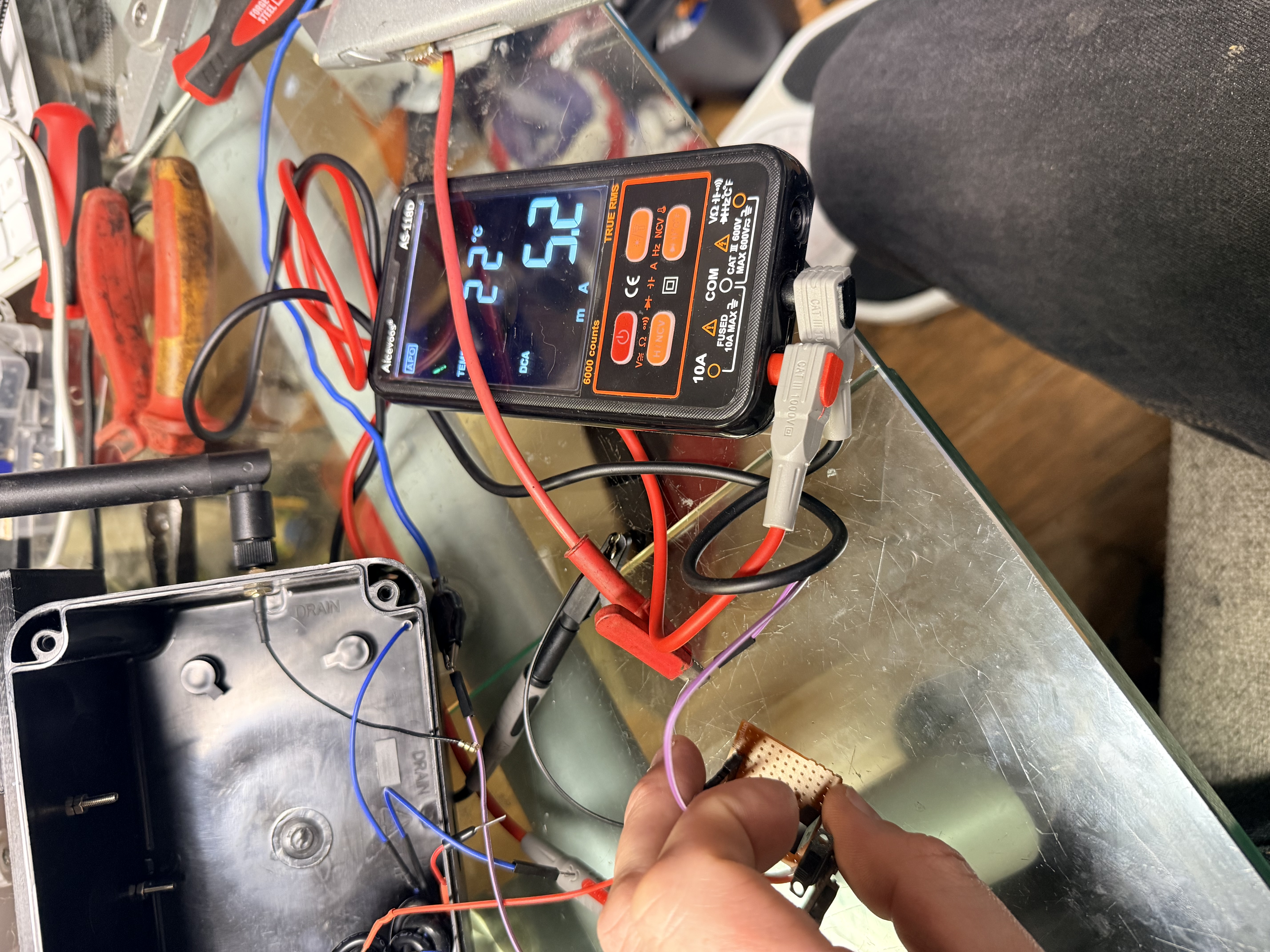 Then settles down to a cool 5.2mA
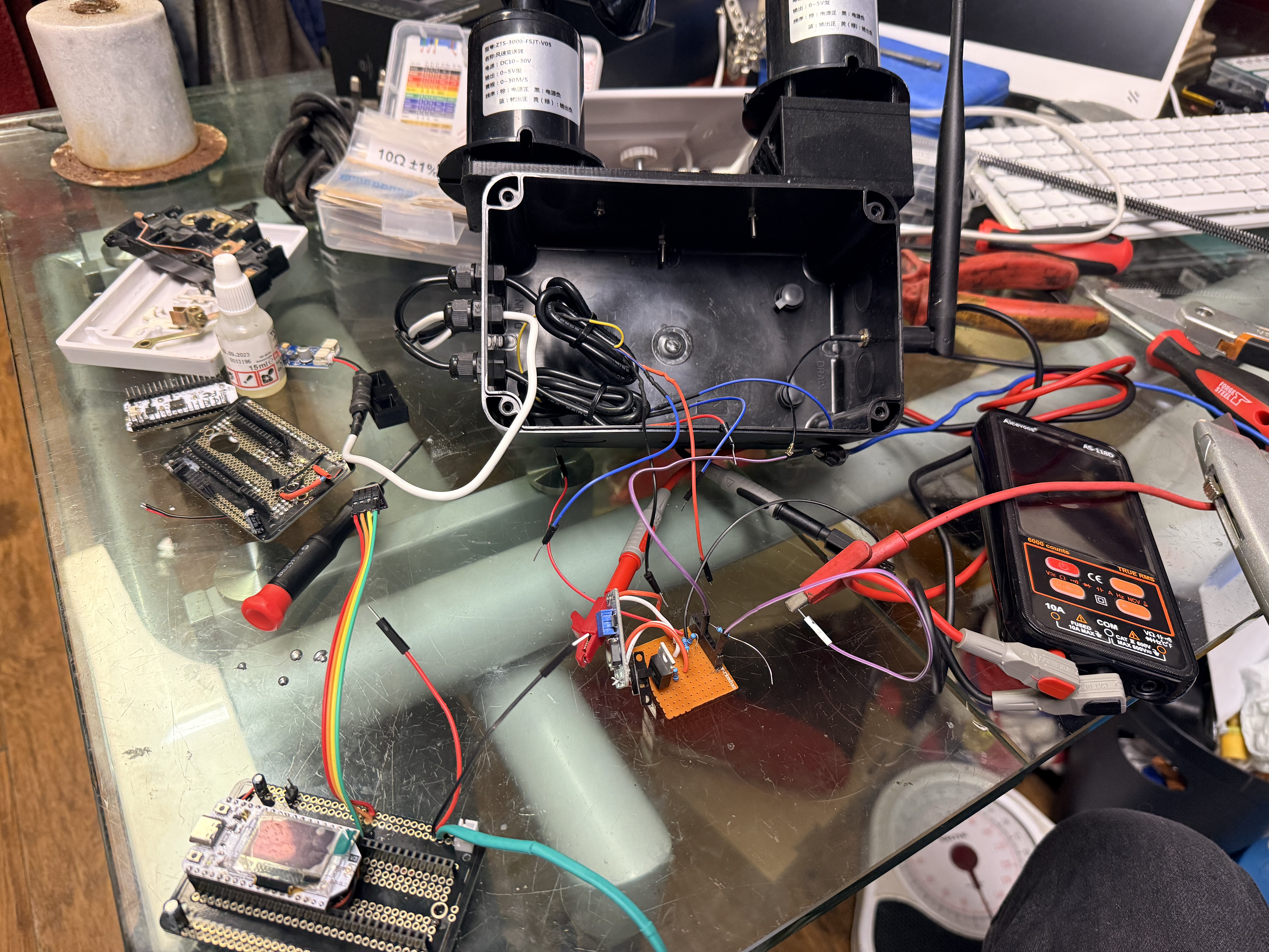 Cable tidying - Before
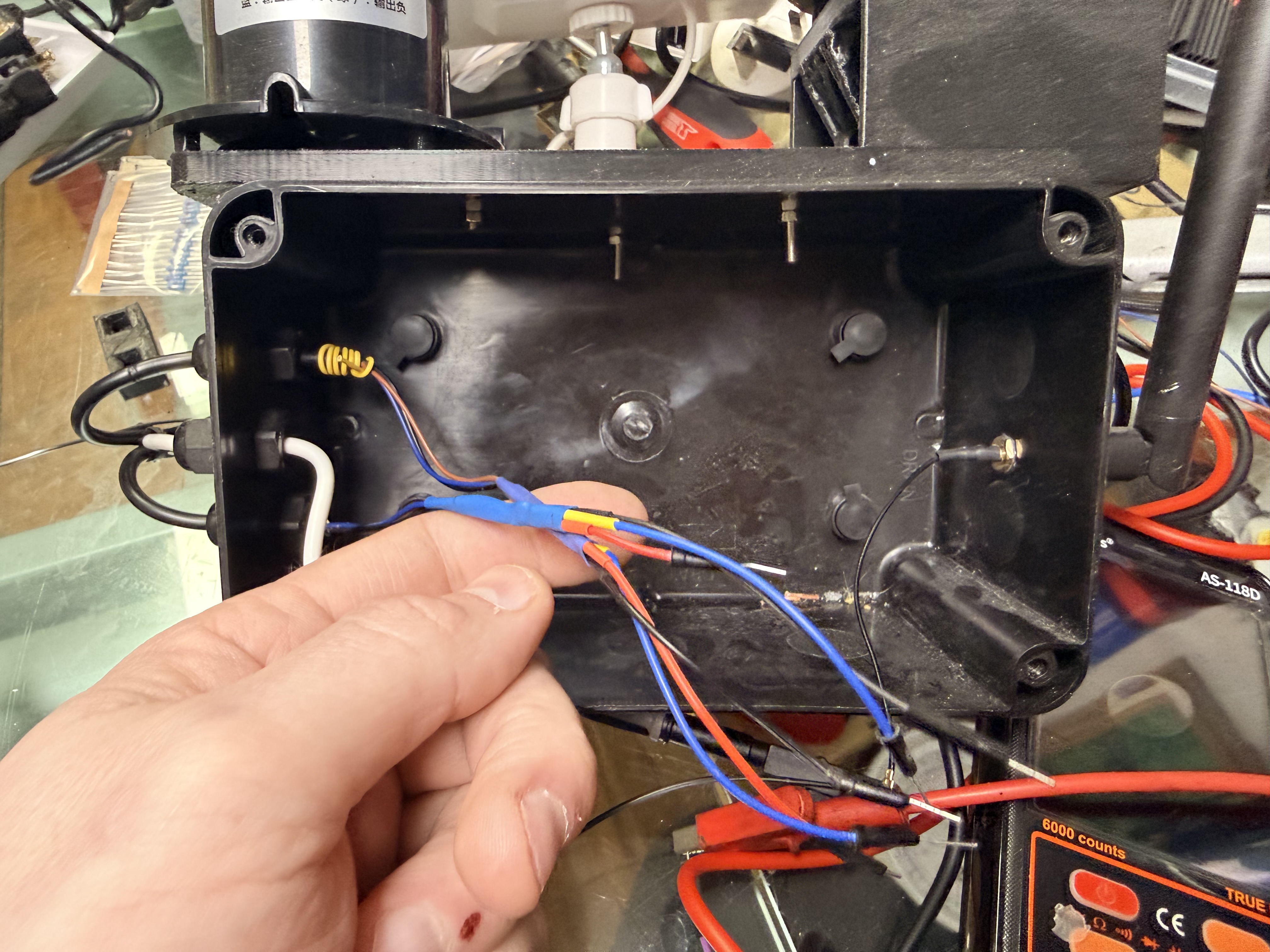 Cable tidying - After
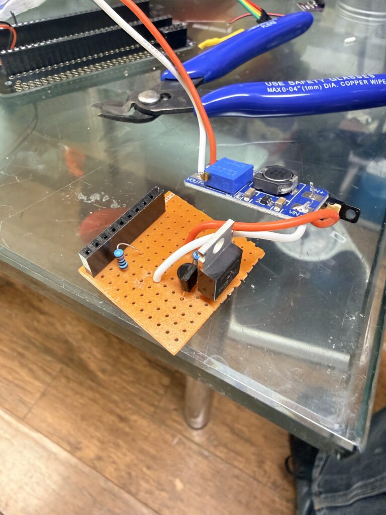
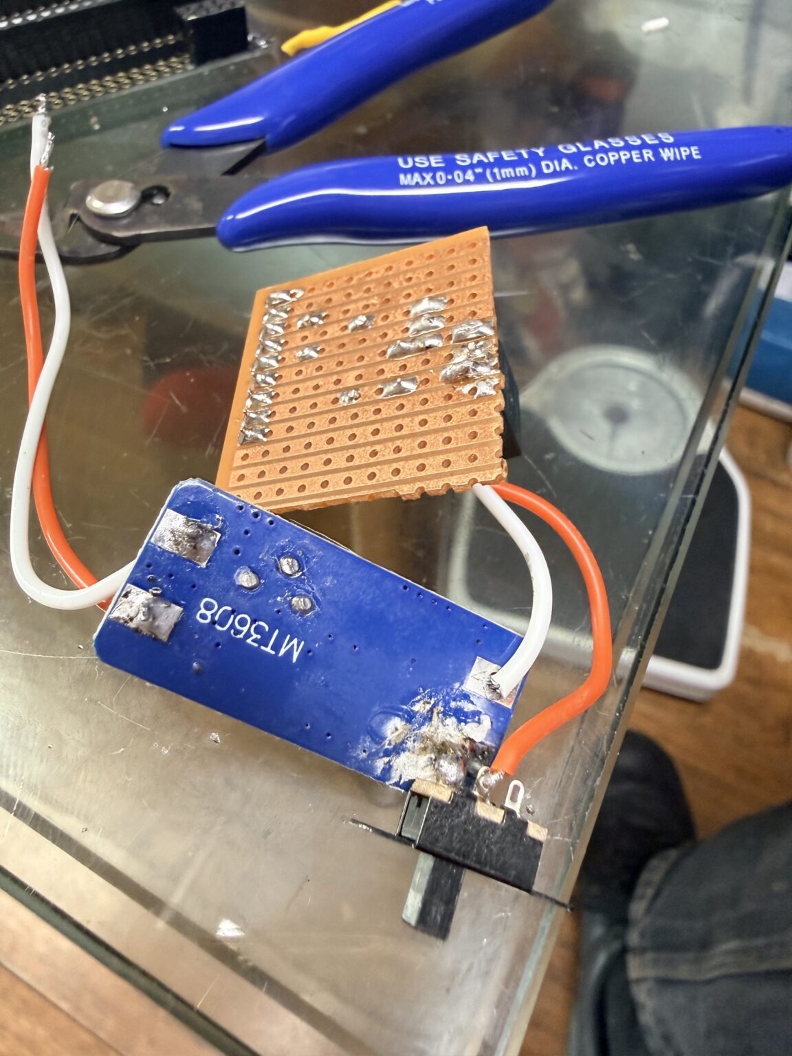
I’m restarting the board from scratch to make it more modular. It’s almost impossible to tell what causes problems when it’s all packed tightly together. My new ethos is the main board is just a mainboard with I/O. The top power rail is going to be just bussed battery voltage. The processor is going to be fed from that through its battery port.
The 3.7V —> 12V DC/DC converter is on a seperate board with its own controller so I should be able to make sure this is working properly independently of the main board which should alleviate some of the problems I’ve been having. That way; either the processor is faulty OR the 12V system is faulty and I can go straight to that and sort it next time.
Apologies for the lack of progress lately, I’ve had a MASSIVE Python development job to do but I should be able to concentrate more on the Weather Station now.
Having trouble with the transistor + MOSFET arrangement. The microprocessor is sending a High signal at the right time – It’s just not switching on the DC–>DC converter to power the anemometer and weather vane. Going to try using new components on a daughterboard. Work for the next two days so if I get some time between shifts tomorrow I’ll do that; or failing that I’ll get stuck in Tuesday-Wednesday when I’ve finished. Work sucks!
Apologies for the long break; extreme work commitments combined with disillusionment with the amount of problems encountered. I’m going to start re-reading the microprocessor code to get familiar with it again and we should be back on track soon. Thankyou to our latest anonymous donor; it’s very much appreciated and will help kickstart continuing the project through to completion. Stand by for updates in the near future!
Stray voltage problem solved! There was the tiniest sliver of solder bridging these two points on the PCB that separate the top power bus from the bottom one we are using for higher voltage. It was almost invisible! Going to spend some time reading the code and getting familiar with it again!
upgrade to the homelab: triple screens!
Apologies, work and life have made it impossible to get anything extra-curricular done lately. I hope to be getting back to diagnosing the stray voltage source soon: off to Scotland tonight for work duties 😳
These issues are an absolute nightmare. There is 3.3V appearing on the high power rail; when nothing is connected. Fighting for time all the time to diagnose this at the moment. Thy will be done!
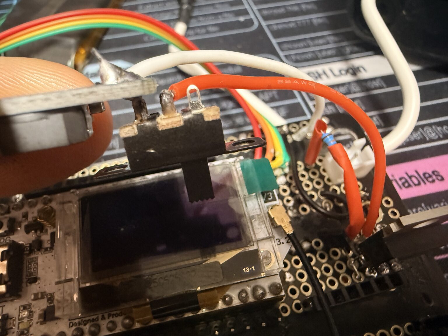
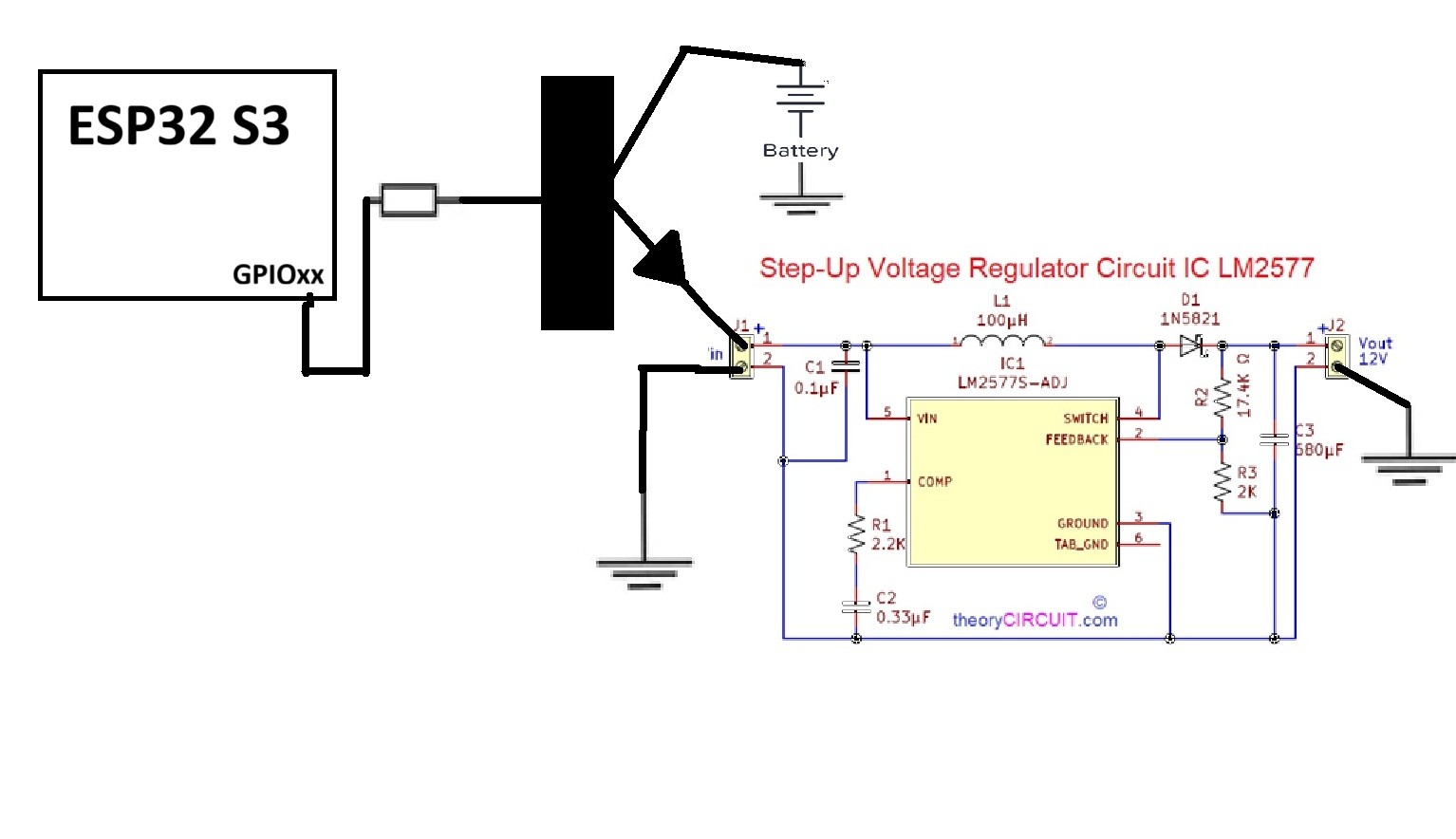
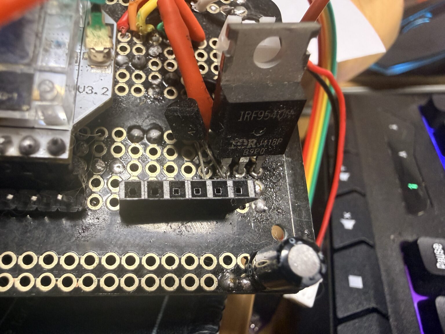
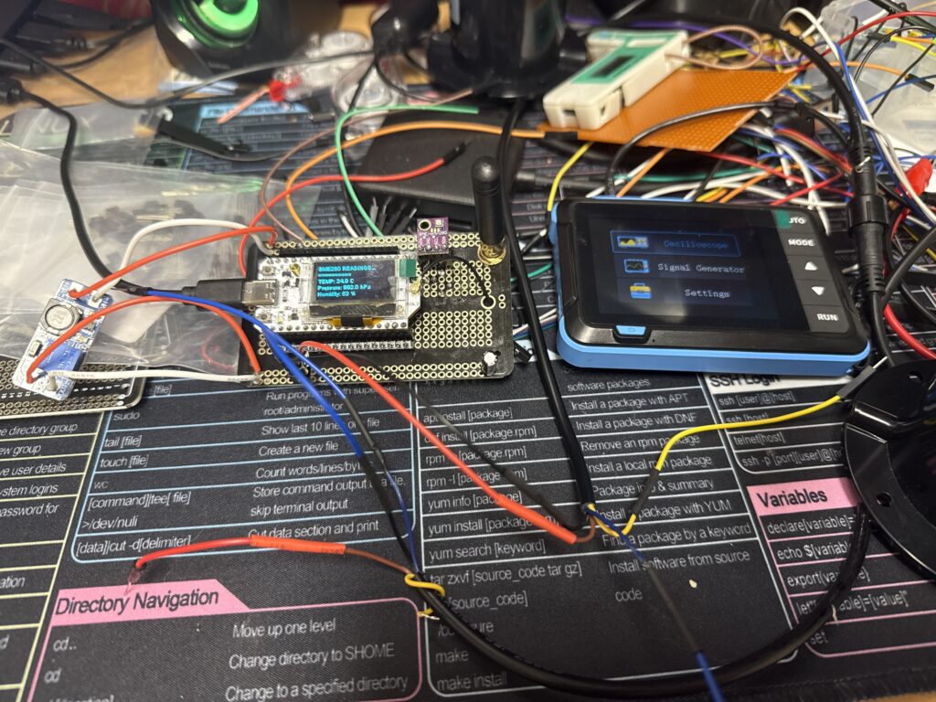
After setting up another controller I created a circuit where the GPIO pin switches on a transistor which grounds the gate on a P type MOSFET. This MOSFET powers the step-up converter that gives us our 10+ Volts for the Anemometer and weather vane sensors.
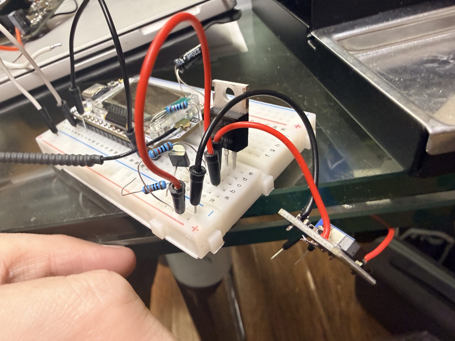
As you can see on the oscilloscope; we get a pretty quick shot of the full voltage we need:
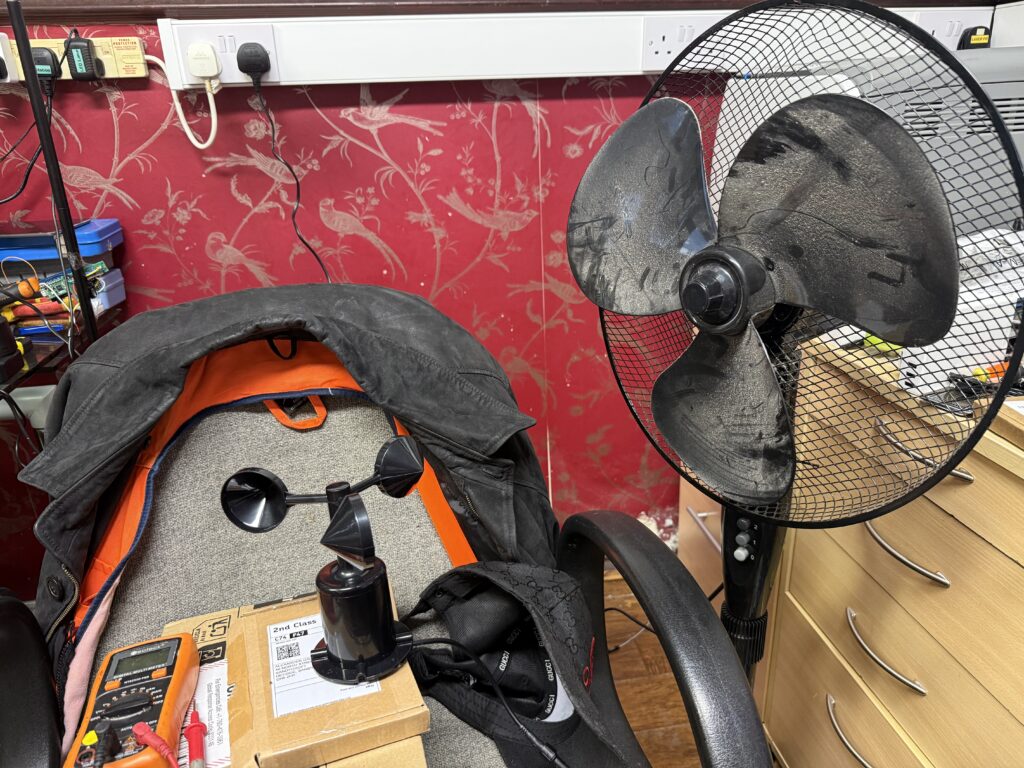
This test was performed with the sensors connected so we know how it should perform in the field.
I then transferred the components onto the PCB of the weather station. I just need to write the code next to give a GPIO output about a quarter of a second before we read the airspeed and direction; then power it off after.
This should hopefully work, and save us a load of power in the long term 😋
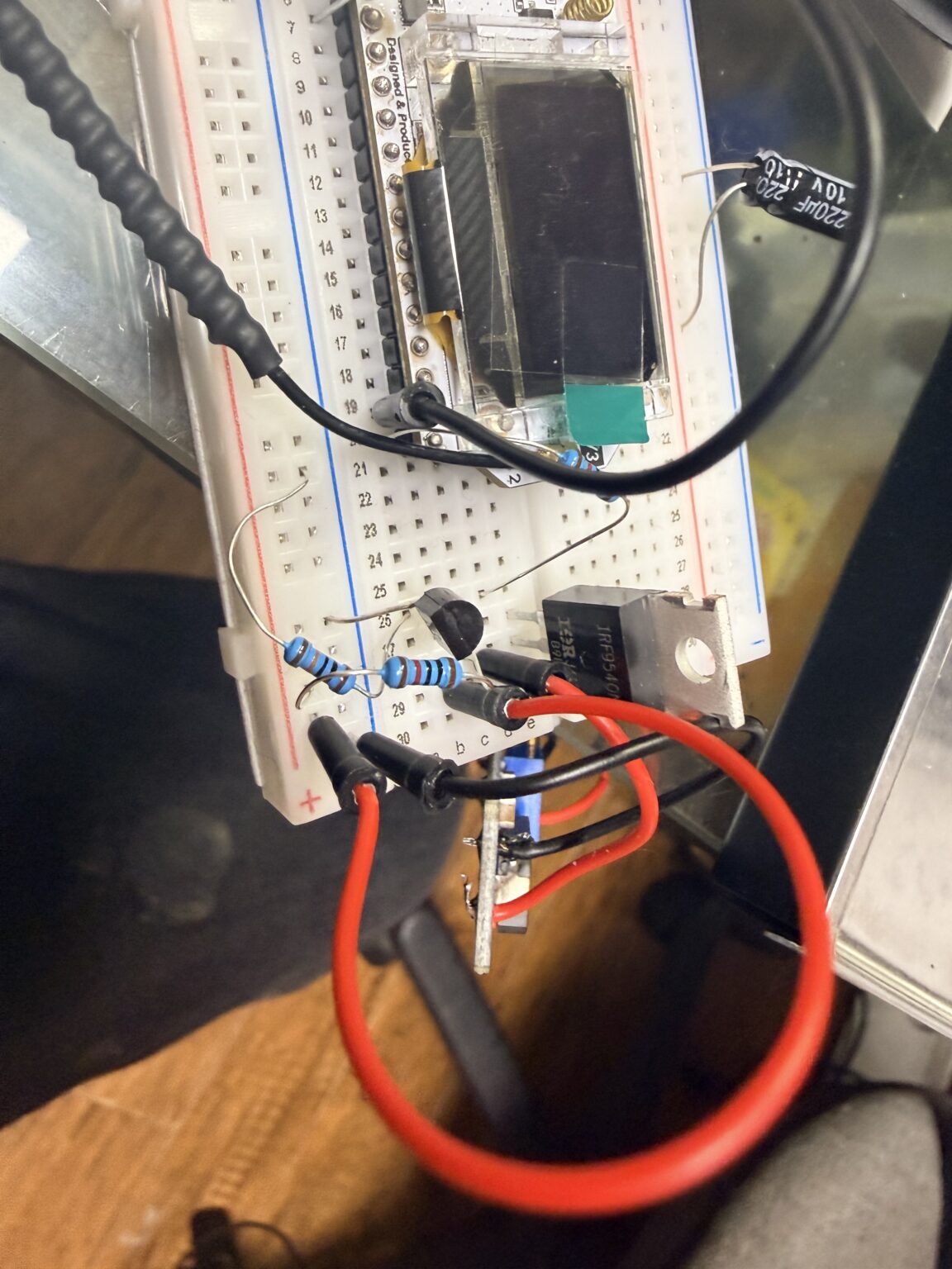
EUREEKA! I just looked in a place I’d already looked twice before and there they were! Hopefully spend some time tomorrow with the breadboard doing some tests to find the best way to lower power usage enough to self-sustain the weather station from the solar panel.
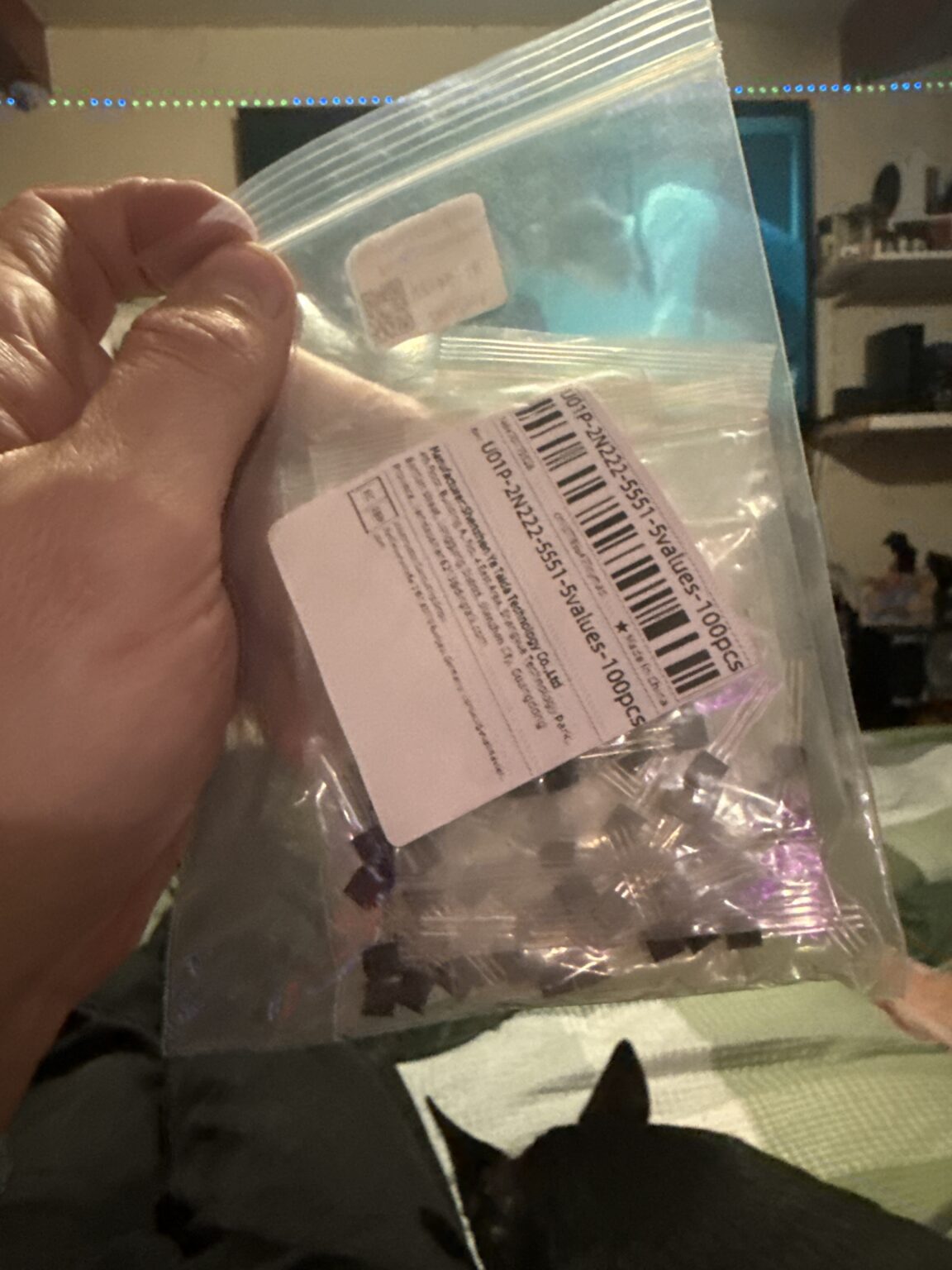
Apologies; I need a transistor to be able to test the MOSFET and my bag of transistors has alluded me! Will continue as soon as I can find them and get a 2n2222 NPN to be able to control the MOSFET.
The voltage booster uses 75mA constantly when powering the anemometer and weather vane. That’s a hell of a lot of power being wasted.
We definitely need to find out if it can be powered quickly for just a second and then have a reading taken before powering down and waiting 30s for the next reading.
The voltage booster only uses 1mA with none of the sensors connected so it’s definitely the sensors that are the problem.
This opens up the option of having a 12v battery as well as the Li-Po that powers the processor and we can use the processor to switch on charging the 12V battery from the 3.7-4.2V battery… when it has enough spare power to do so. We can also then use the processor to switch the 12V battery directly into the sensors every 30 seconds ready to take a reading. This way should give the sensors plenty of power the instant they need it as opposed to firing up the voltage booster every 30 seconds and just hoping it stabilises fast enough for the wind readings to be taken. We can also disable the anemometer and weather vane from being powered up at all when the 12V battery loses charge so that doesn’t go too flat and damage itself.
Absolutely fighting for time lately with work being so busy. I have now moved GPIO1 and GPIO2 to GPIO3 and GPIO4 both physically and in the software so I can hopefully get battery level reading functionality to work. I had to work out a correction factor using trial and error because I don’t know what voltage divider is used on the Heltec board for the battery sensor so the code I use to read the battery level needed a correction variable between 2.00 and 5.00 which had to be guessed, compiled, uploaded to the Heltec, wait for the reading to appear and then to work out how much higher or lower I needed to change the number to and do the whole process again for the next trial. It was around 5am when I got to this stage so I got it pretty much bang on and had to give up without verifying it stayed accurate when the battery level changes.
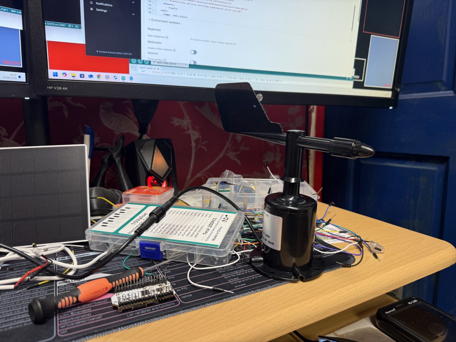
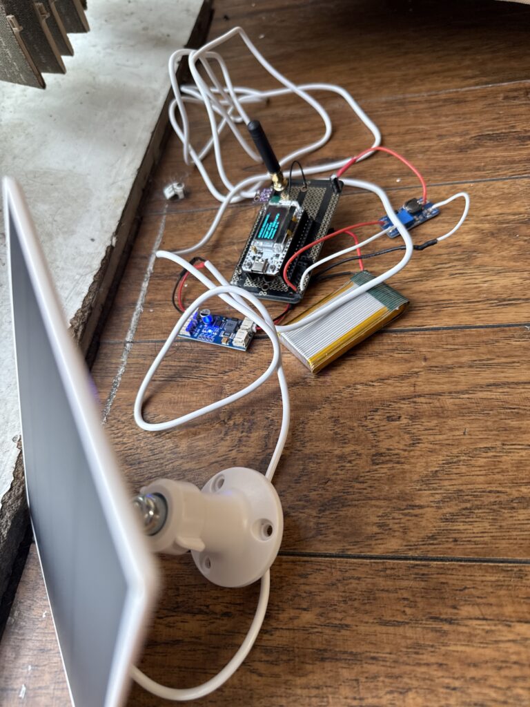
Proof of concept of the weather data being displayed on the website with the weather station completely wire-free in the garden: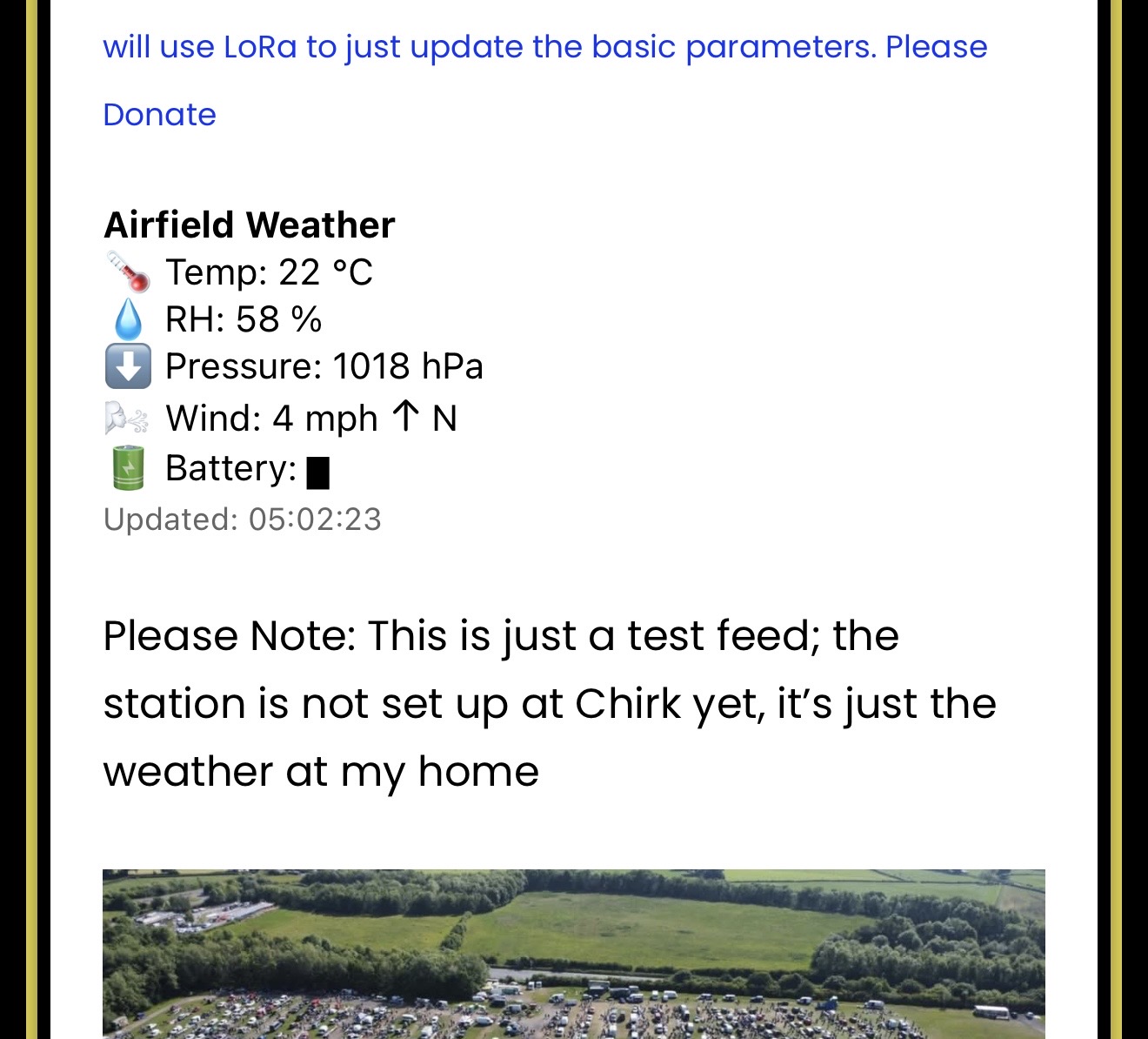
I have installed an N type MOSFET connected to GPIO19 that I’m hoping to use to switch on the low-side of the step-up DC-DC converter that generates the 13V DC we need for the wind speed and direction sensors. For some reason the output is only ever about 1-3V DC which is no use whatsoever.
I thought the step-up might have gone faulty so I’ve tried another one with the same result. Again I ran out of time at 0430am so had to give up for the time being. I might try using a transistor to switch the MOSFET and see if that helps lower the resistance on it or worst case scenario I might have to try using a physical relay to cleanly switch the step-up on with no resistance in order to get the voltage we need 😩😮💨
Apologies for the lack of updates lately; I’ve been trying to use 100% of every minute I have fixing problems and getting things done rather than writing about them. I’m afraid I’m working away this week and then going to Thailand for nearly three weeks so it’s going to be a bit quiet until later in October I’m sorry.

Have run into some hurdles. The first being that the station drains its battery overnight and doesn’t seem to come back to life when the sun comes back. Another being that the onboard battery sensor is meant to use GPIO1: the same pin I have used to measure the anemometer. They can’t both use the same input!
When plugged into USBC: I noticed that the Heltec board is drawing 500mA; that’s way too much for the solar panel to cope with. I think I only measured about 45mA of power generation on a gloomy day.
The processor itself is not a problem; it really does sip power. The main suspect is the 3.3V to 13V converter. It’s not meant to use a lot of power but maybe because it’s a cheap Chinese one it has some sloppy electrics. The next logical option to deal with this is to implement a way of switching the 13V generator off all of the time except when the sensors are being read every 30 seconds. Easier said than done.
I’ve defined the data being sent from the weather station to the server:
| Data Item | Description |
|---|---|
| BYTE 1 | |
| Bit 1-6 | Wind Speed 0-64mph |
| Bit 7-8 | Wind Direction (Bit 1 and 2 of 3) |
| BYTE2 | |
| Bit 1 | Wind direction - (Bit 3 of 3) |
| Bit 2-7 | Temp -20 to +43'c |
| Bit 8 | Humidity (Bit 1 of 7) |
| BYTE3 | |
| Bit 1-6 | Humidity - (Bit 2-7 of 7) |
| Bit 7-8 | Pressure - (Bit 1-2 of 6) |
| BYTE4 | |
| Bit 1-4 | Pressure - (Bit 3-6 of 6) |
| Bit 5-7 | Battery Level - 8 Stages - (3 Bits) |
| Bit 8 | Error present - 0=No 1=Yes |
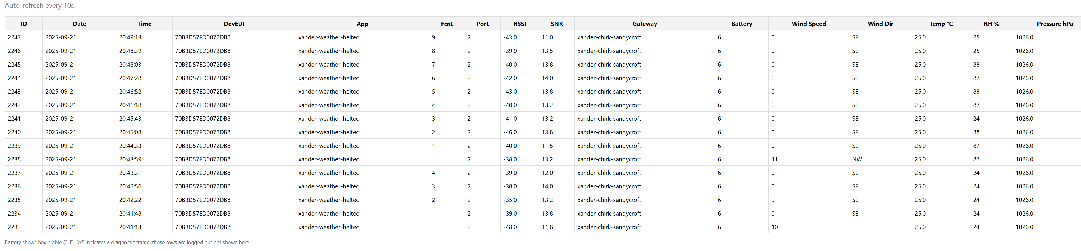
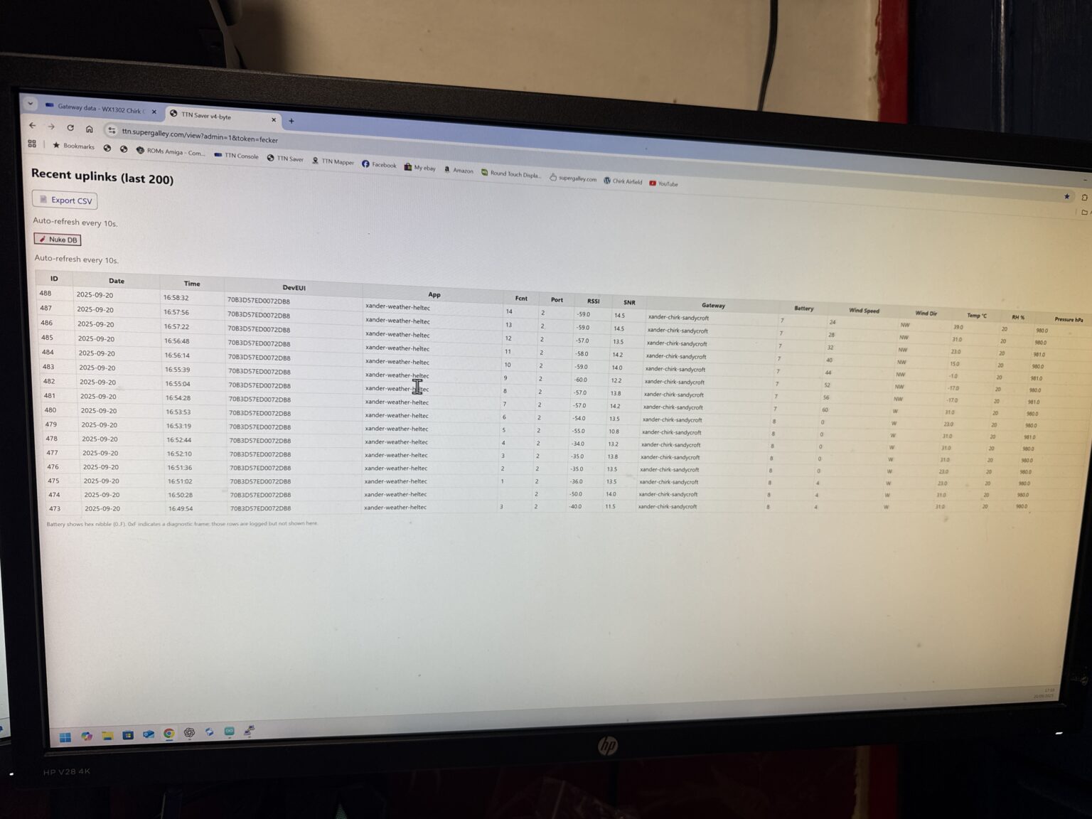
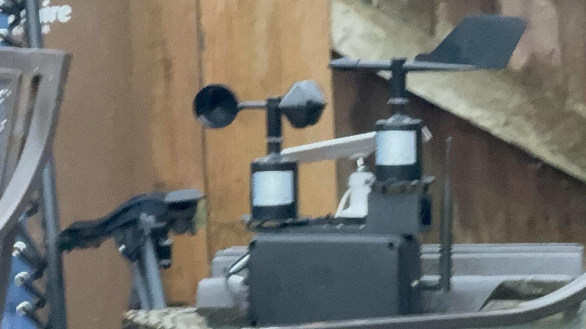
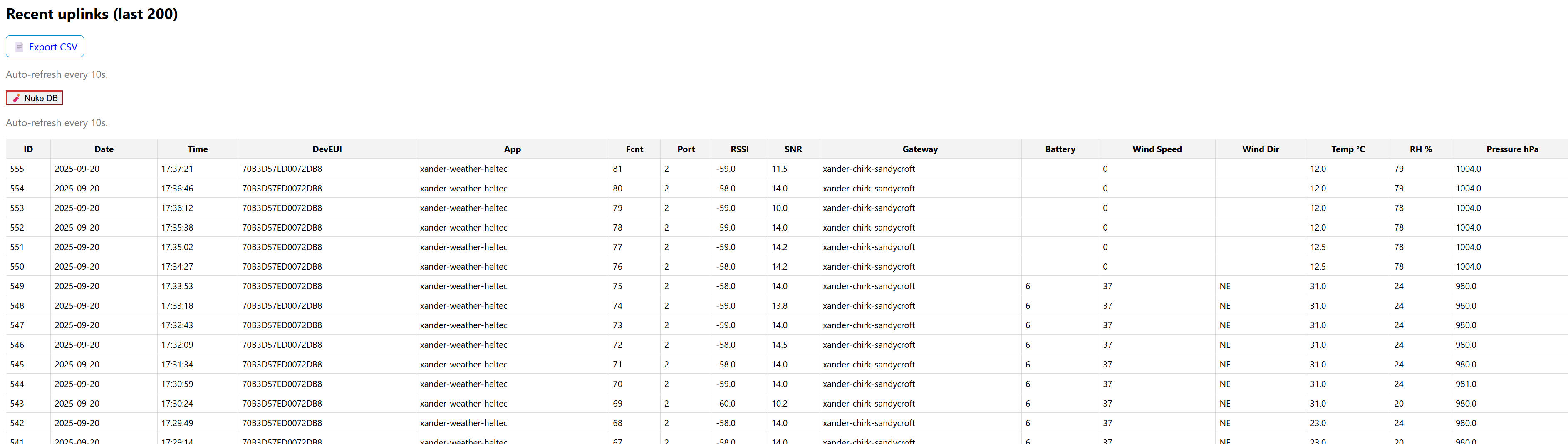
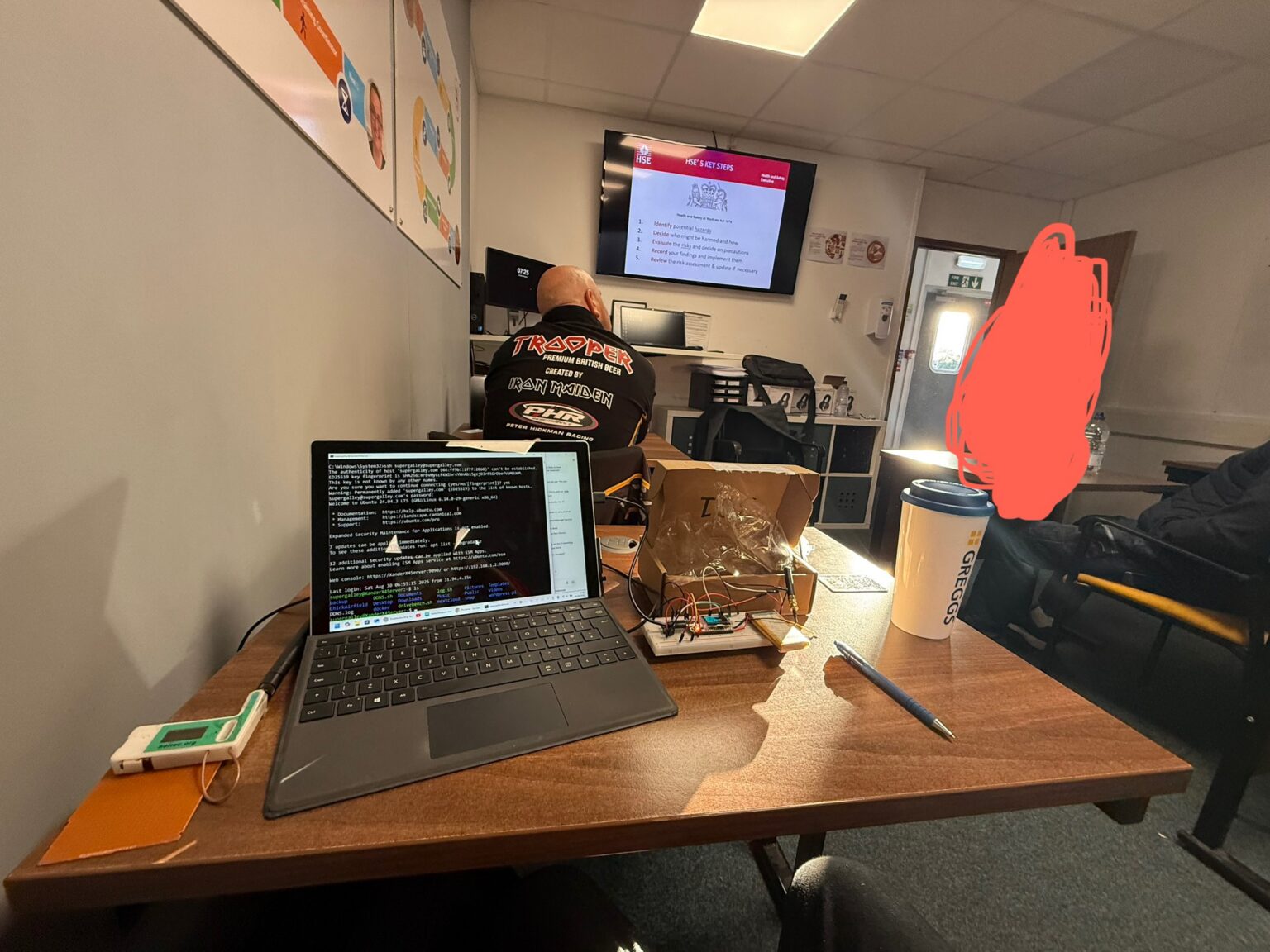
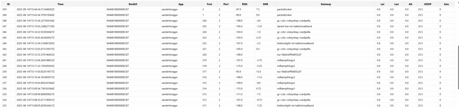
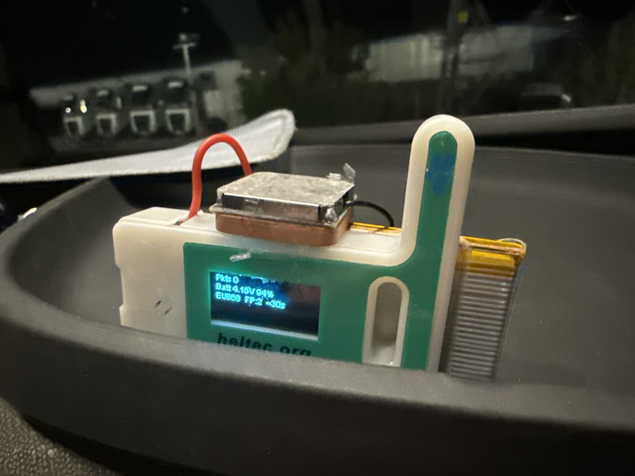
It’s getting real! Starting to look like a weather station. It’s outside in its sealed enclosure with everything hooked up. Should be able to keep an eye on it at the web page ttn saver. The data is being received through my TTN gateway:
Although it’s not right: the 4 byte payload is probably off a ‘bit’ – literally. That’s upset everything so the wind speed, direction, temperature, humidity and pressure are off but after some tweaks it should just pop right into place in theory. That’s all for today, off out on birthday celebrations so I’m hopefully going to be over the drink-program limit very shortly 🤪
Quick update. Altered the python code for the decoder and it’s looking more credible:
Still a bit of work to do but we are seeing real results now
An edit to the sensor mount needed to be done. The base was too flexible and with the close tolerances the weather cock could come into contact with the anemometer.
Version 2.0 is now printing: with a thicker base and the weather vane platform is raised by about 20mm to ensure maximum clearance between sensors.
Head scratching day. It will join the LoRaWAN no problem using an old program I used for testing if there was LoRaWAN available at Chirk just using the Heltec board as a scanner. But use that same code to try and join LoRaWAN to send our four bytes of weather data; it won’t ever join despite not getting as far as trying to send the data. Not making a lot of sense. Spending hours trying new methods to jumpstart it.
Latest program loop()
void loop() {
// &
checkPauseButton();
if (deviceState == DEVICE_STATE_JOIN) {
delay(1); // stay responsive during join windows
} else {
delay(300);
}
if (paused) { delay(50); return; }
// &
float tC=nanf(“”), rh=nanf(“”), pres=nanf(“”);
if (bmeAddr) {
tC = bme.readTemperature();
rh = bme.readHumidity();
pres = bme.readPressure() / 100.0f; // hPa
}
uint16_t aCounts = readADCoversample(PIN_ANEM, 64);
float vA_in = adcToVolts(aCounts) * DIV_K;
float vEff = (vA_in < ANEM_ZERO_DB_V) ? 0.0f : (vA_in – ANEM_ZERO_DB_V);
float wind_ms = (vEff / ANEM_MAX_V) * ANEM_MAX_MS;
if (wind_ms < 0) wind_ms = 0;
float wind_mph = wind_ms * MS_TO_MPH;
uint16_t vCounts = readADCoversample(PIN_VANE, 64);
float vV_in = adcToVolts(vCounts) * DIV_K;
const char* dir = mapVaneNearest(vV_in);
uint16_t batt_mV = BoardGetBatteryVoltage();
float batt_V = batt_mV / 1000.0f;
float batt_pct = (batt_V – BATT_EMPTY_V) * 100.0f / (BATT_FULL_V – BATT_EMPTY_V);
if (batt_pct < 0) batt_pct = 0; if (batt_pct > 100) batt_pct = 100;
if (bmeAddr) {
oledStatus(“Temp: ” + String(tC,1) + ” C ” “Hum: ” + String(rh,0) + “%”,
&
} else {
oledStatus(“Temp: –.- C Hum : — %”, “Pres: —-.- hPa”, “”, “”, “”);
}
oledStatus(&
display.display();
// — LoRaWAN state machine (fixed) —
static bool loraInited = false; // guard: init only once
static bool joinIssued = false; // guard: send join only once
switch (deviceState) {
case DEVICE_STATE_INIT: {
if (!loraInited) {
LoRaWAN.init(loraWanClass, loraWanRegion);
LoRaWAN.setDefaultDR(0); // SF12 join uplink (safe)
joinStartMs = millis();
joinIssued = false;
loraInited = true;
// Optional: brief hint
oledStatus(“”, “”, “”, “LoRa: starting WAN join”, “EU868 / OTAA”); display.display();
}
deviceState = DEVICE_STATE_JOIN; // advance once
break;
}
case DEVICE_STATE_JOIN: {
    if (!joinIssued) {
      LoRaWAN.join();                    // send the Join-Request once
      joinIssued = true;
    }
    uint32_t elapsed = millis() - joinStartMs;
    if (elapsed > 90000 && !joined) {
      oledStatus("", "", "", "No gateway yet", "Check antenna / move"); display.display();
    } else {
      static uint8_t dot=0;
      String tail = (dot%4==0?".":dot%4==1?"..":dot%4==2?"...":"");
      oledStatus("", "", "", "LoRa: joining " "EU868 / OTAA"+tail, ""); display.display();
      dot++;
    }
    break;
  }

  case DEVICE_STATE_SEND: {
    if (!joined) {
      joined = true;
      oledStatus("", "", "", "LoRa: joined  ADR:ON", "Preparing first uplink…"); display.display();
    }
    prepareTxFrame(appPort);
    LoRaWAN.send();
    uplinkCount++;
    oledStatus("", "", "", "Weather data sent", String("Packet (4B) No. ")+String(uplinkCount)); display.display();
    deviceState = DEVICE_STATE_CYCLE;
    break;
  }

  case DEVICE_STATE_CYCLE: {
    txDutyCycleTime = appTxDutyCycle + randr(-APP_TX_DUTYCYCLE_RND, APP_TX_DUTYCYCLE_RND);
    LoRaWAN.cycle(txDutyCycleTime);
    deviceState = DEVICE_STATE_SLEEP;
    break;
  }

  case DEVICE_STATE_SLEEP: {
    LoRaWAN.sleep(loraWanClass);
    break;
  }
  // IMPORTANT: do NOT fall back to INIT here
  default: {
    break;
    }
   }
  }
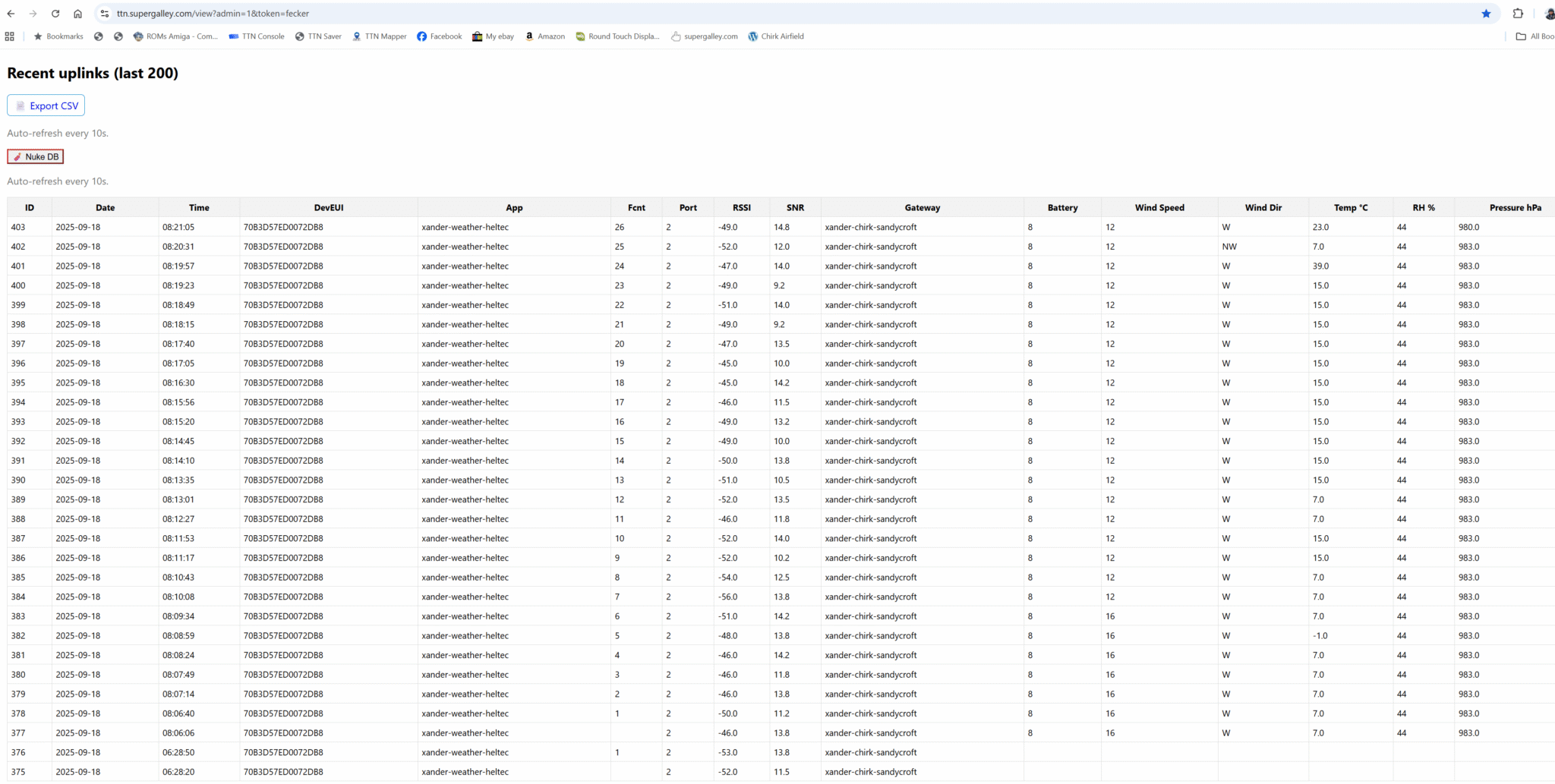
Little breakthrough… the website is collecting data 😊😊😊😊
GG
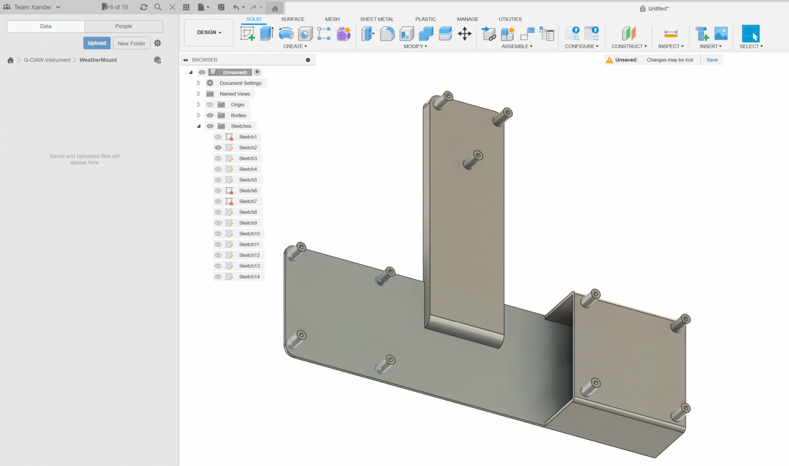
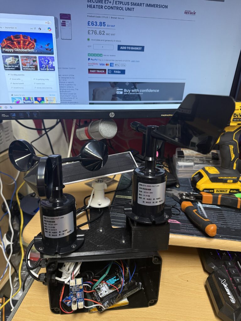
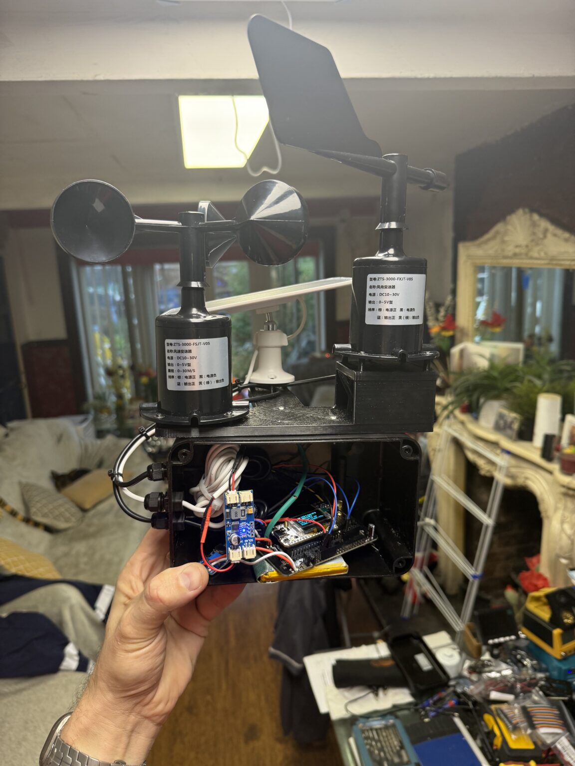
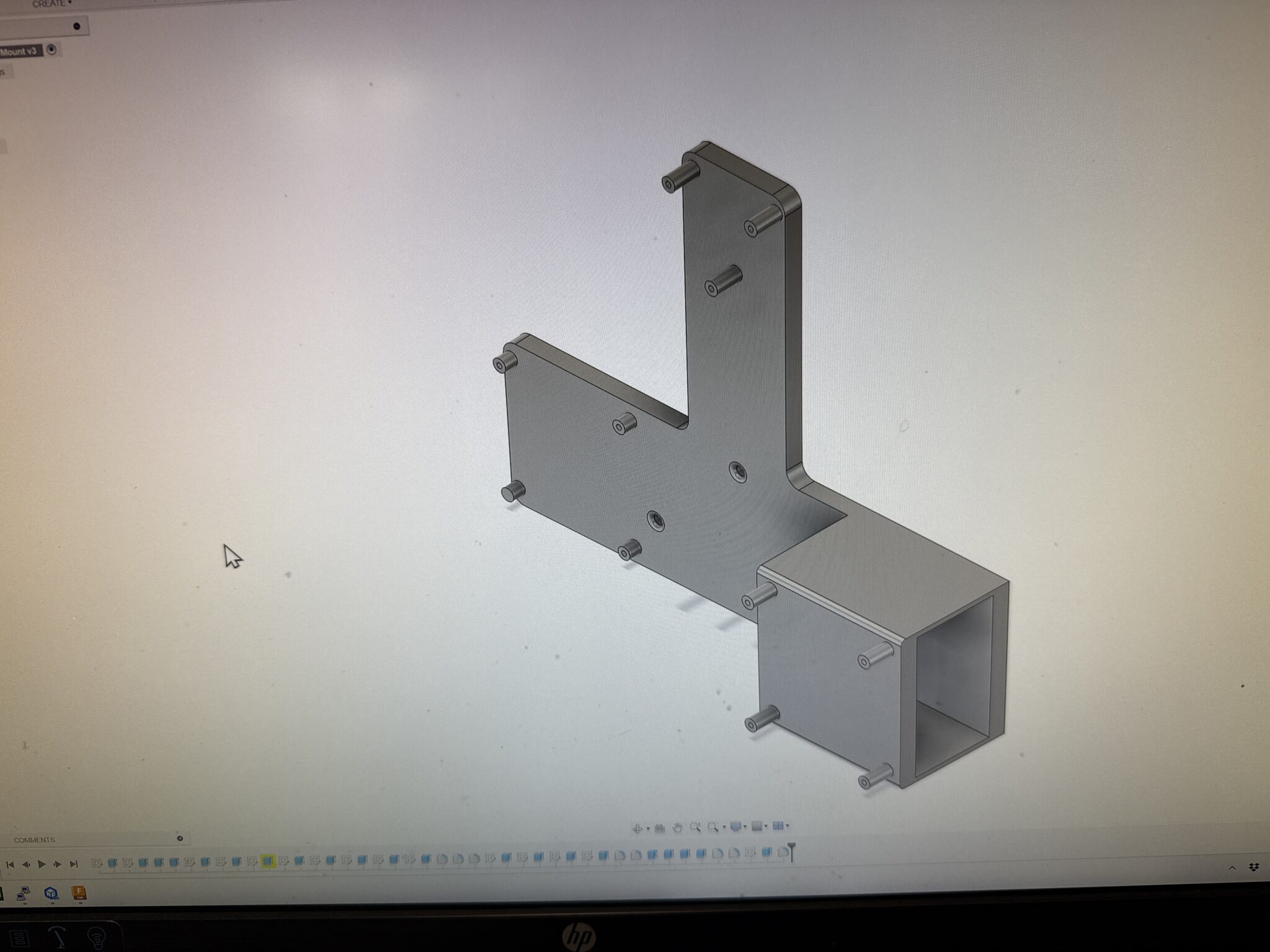
Of course I have to make a way of mounting all the sensors. Here is a model I designed which according to my calculations should mount the anemometer on the left, the wind vane on the right and the solar panel at the back; all tightly arranged so that they are really close; but don’t interfere with each other.
The only other thing to consider is the Temperature and humidity (& pressure) sensor. If I leave that in a weatherproof box it’s likely to very quicky read wrong on all three fronts. It needs very good ventilation so as not to heat up, ventilation in order to detect the humidity from the outside air and also if it’s enclosed the pressure could also be slightly off if there& box. I’m thinking of sending it up a little tube thats attached to the side of the weather station with metal housing and maybe some spray foam on the metal surfaces so the heat from the sun doesn’t just radiate straight through and alter the readings. It needs to really be metal because you have to protect the sensor from radiation or it will have a short life and need frequent replacement. I might get the weather station up and running with the temp/pressure/humidity sensor just attached to the board at first though – then we will at least get our most important data- wind speed and direction. Out of time again for today so will hopefully carry on tomorrow. Made some good breakthroughs today 😊
Its coming off the computer and into the real world 🙌😆
Nearly done 🙌
After another three days of Internet outage; it finally came back on early this morning. 🤬. DAMN YOU BT Openreach!!!
It makes it impossible to code with no Internet; I can’t get my resources so the second I run into a problem I’m completely
stuck until I can get back online. In work for another two days now and should be able to get it finished around this weekend!
After a VERY busy week at work; BT let me down; my Fibre-optic connection went off in the early hours of Thursday 11th until this morning &
taking with it ChirkAirfield.com, supergalley.com, Nextcloud, Jellyfin, Pi-Hole, Traefik and another web interface I use for important business.
Hoping to make the final code ready anytime soon. I have all the sensors working and reading. I have done nearly all the backend work on my server to
receive the data at https://ttn.supergalley.com and I just need to get the weather station to send it’s data over LoRa. Easier said than done!
Standby for updates…
Still working on it!!!
0629. Looking very close to a working product. Just need to program the LoRa interface now!
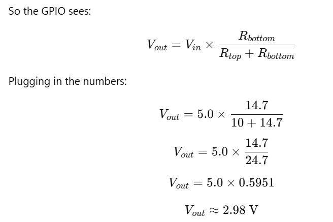
Done quite a bit of coding and soldering today. I have allocated GPIO 1 for the anemometer and GPIO2 for the wind direction sensor.
I have put both these sensors into the respective GPIO Analogue to Digital Converter (ADC) pins through a 10,000 Ohm resistor and I have
also grounded each GPIO pin with a 10k and a 4.7k resistor. The GPIO pins work at 0 to 3.3 volts; any more will fry them and either burn
the input/output on that pin or destroy the whole chip so I used this arrangement to divide the voltage to the 0 to 5 Volt signal we get
from the sensors never gets seen as more than 3.3 Volts at the actual pin but it still gives a dead accurate representation of the actual
signal if we just use maths to calculate the original voltage from the voltage the pin actually sees… so it sees 2.98 Volts when
the sensor gives 5 Volts – obviously it’s hard to get the exact resistor values to get it bang on 3.3V = 5V and it’s
a good idea to drop the voltage a bit lower that 3.3V so there’s less chance it will ever reach it if the sensor goes a tiny bit
over!
Here is the mathematic formulas for the voltage division on a 5V input:
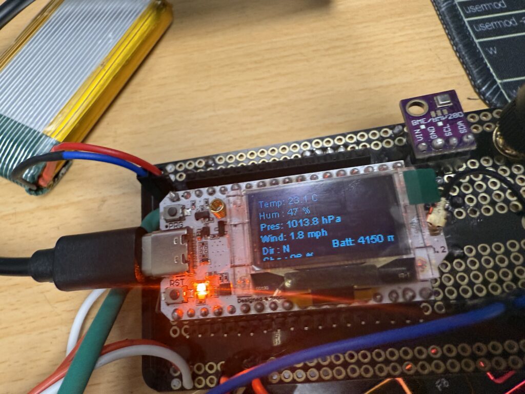
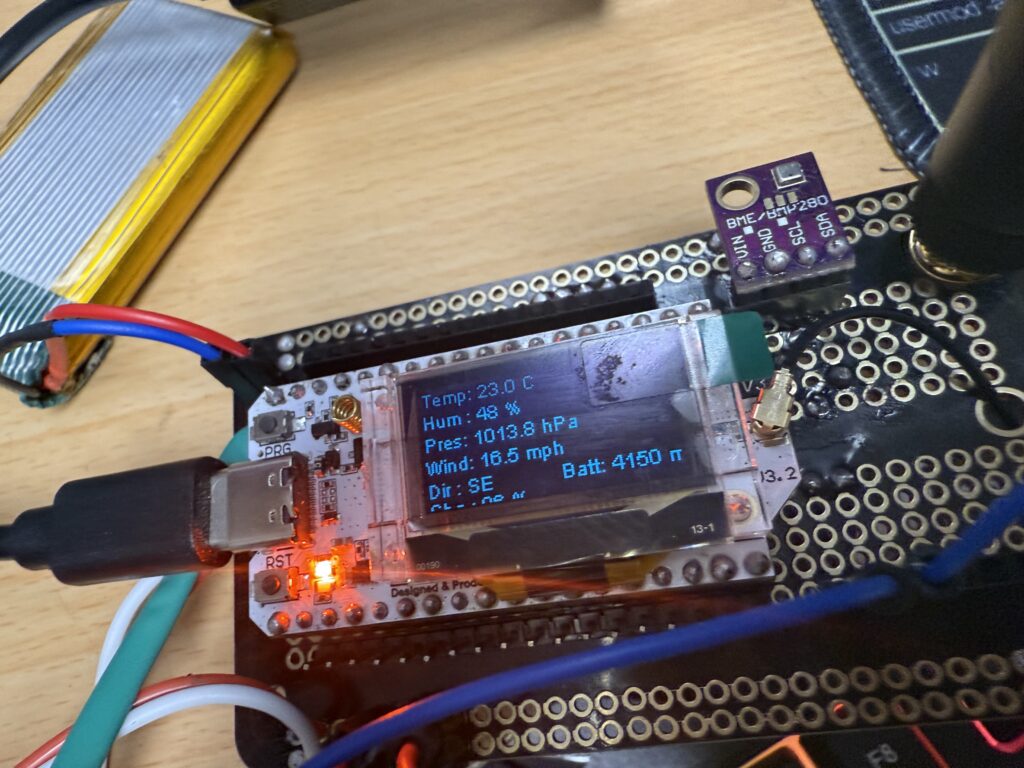
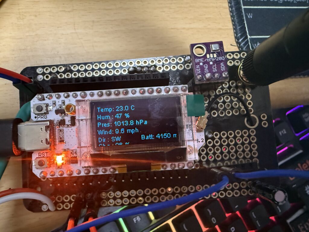
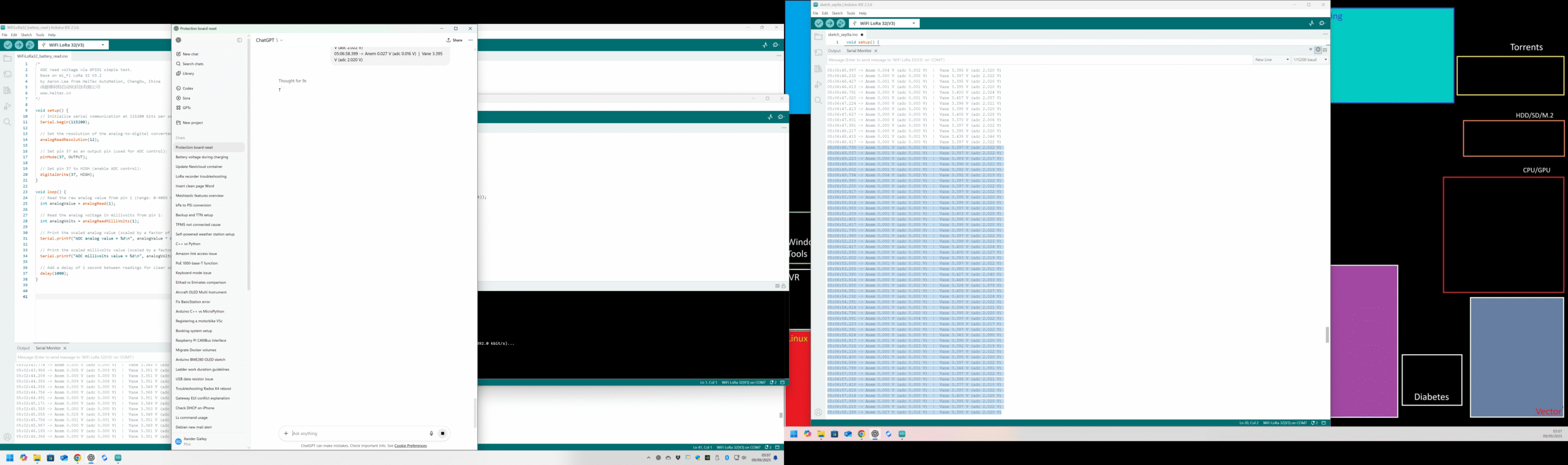
Things are really starting to progress now! Here is some of the data I captured in the programming environment:
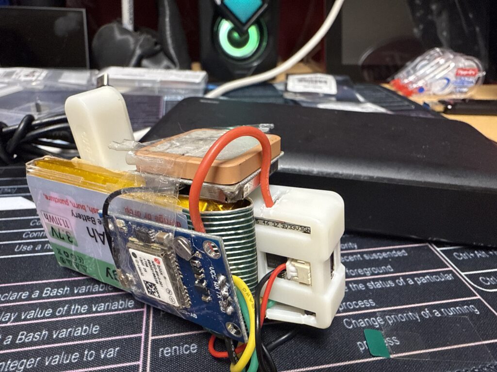
I have been working on the project over the last few days; just not posting about it. I ran into a bit of a problem: The only power pin available was a 3.3V pin from the Heltec V3 board as it does have a 5v pin & provides 3.7-4.2V and that would fall short.
I devised this workaround: I chopped the battery wires and kept the original plug that powers the Heltec board and added two more: one to a solar charger board that will control the varying inputs from the solar panel and cleanly feed 4.2V to the battery to charge it only if it receives enough solar power to be able to do that. I also created a branch that goes directly to the step-up buck that will give us our 12V we need to supply the anemometer and wind direction sensor. Fingers crossed that this will all run happily through the night off the battery when the sun goes down. There is an extra port on the solar charger I can easily add an extra battery to at a later date if it starts running out of charge before morning.
I’ll have to decide if the BME280 (temp/pressure/humidity) will be ok where it is now next to the Heltec board or if I need to mount it remotely. I can either choose to add ventilation to the main box or to keep it well sealed and put the sensor outside but still protected from solar radiation and rain.
What I need to do to finish the project:
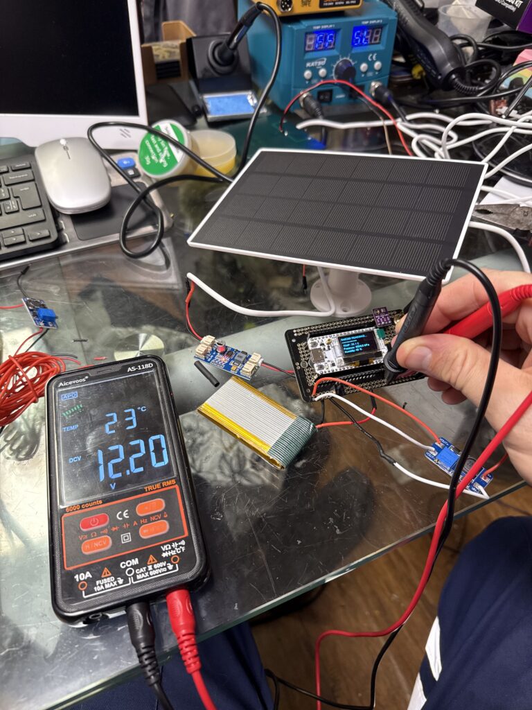
It looks like it’s charging ok as even on a dull day the red light on the solar charger board has changed to blue. I hope this means charging 🤞
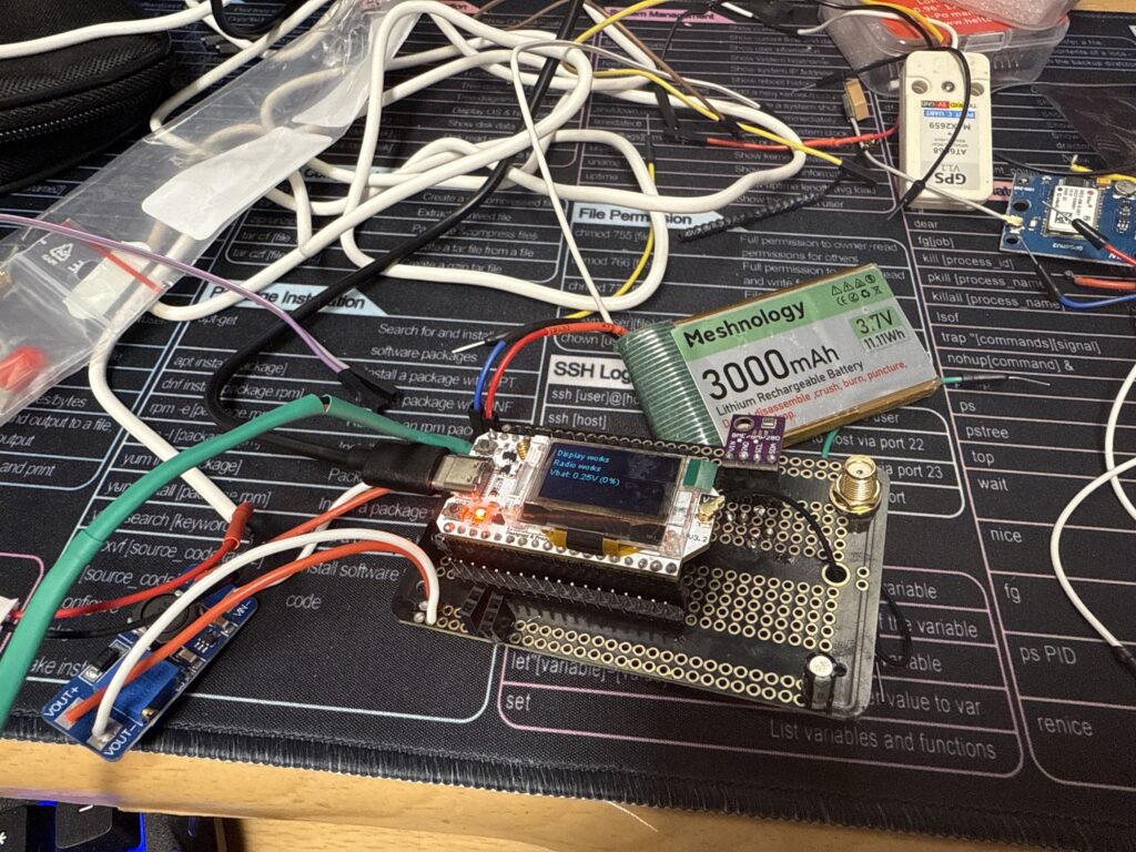
Pulled an all-nighter 😵 I’ve bought a solderable breadboard to house the microprocessor and all of the interfaces:
This should make it look quite tidy. The smaller board on the left is a buck converter to give us 12V from our 3.7V battery that the anemometer and wind direction sensors need. I only found out they need this higher supply voltage after they arrived!
I have driver CPC training today so I should have some time to do some major coding
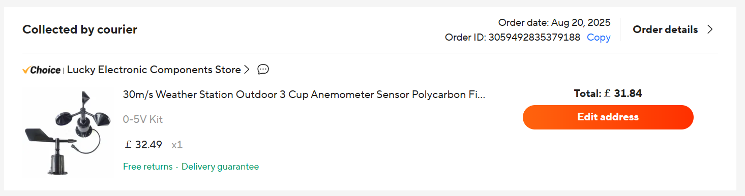
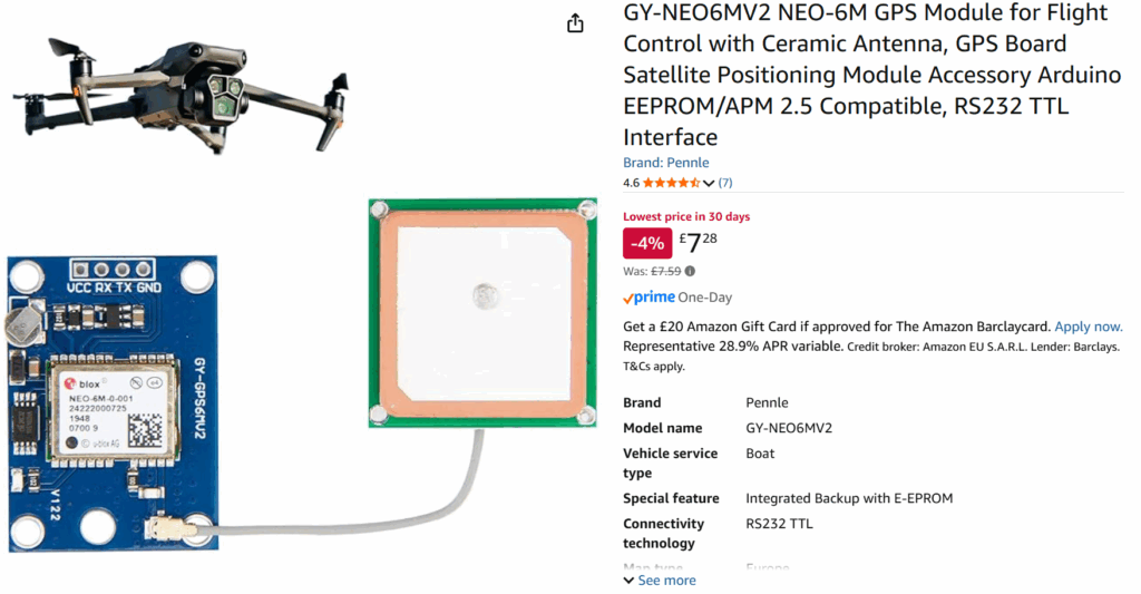
Anemometer and weather cock arrived from China today. Massive hurdle: there was nothing written on the advert but on the devices themselves they both say “DC10-30V”.
Not the end of the world; it just means we’re either going to have to use a 12v motorcycle battery or maybe three 3.7v lithium batteries in series to give us 11.1V. It just means we can’t run the station off a single LiPo battery.
It’s kind of a blessing because I would like to have 5 Volts available to the system; the Heltec ESP32’s battery only provides 3.7-4.2v which some 5V components can be fussy about.
I just have a fair bit of coding to do now to get the sensors working. I’ll also see what kind of voltage the sensors will work
down to and if that 10V minimum is accurate.
Has anyone seen my multimeter???
I’m working on integrating all of the sensor data with the LoRaWAN functionality today – trying to make it as modular as possible in order to make it easier to set up, get it running and keep it running; especially if any one thing goes wrong such as a duff sensor.
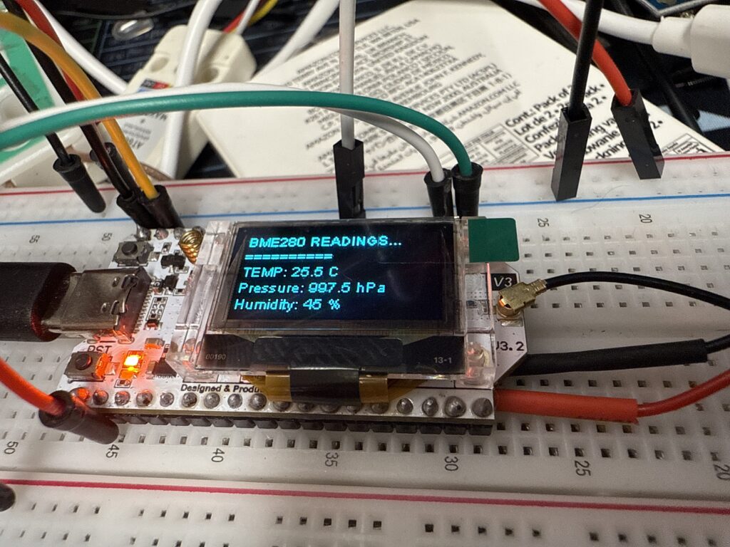
Managed to get the tiny BME280 Temperature/Pressure/Humidity coded to work with the ESP32 processor and display on the screen.
Deep into getting the GPS receiver working on the Gateway today. It will help a lot with synchronising timings
Starting to work on coding the sensors now. First the BME280 temp/pressure/humidity module.
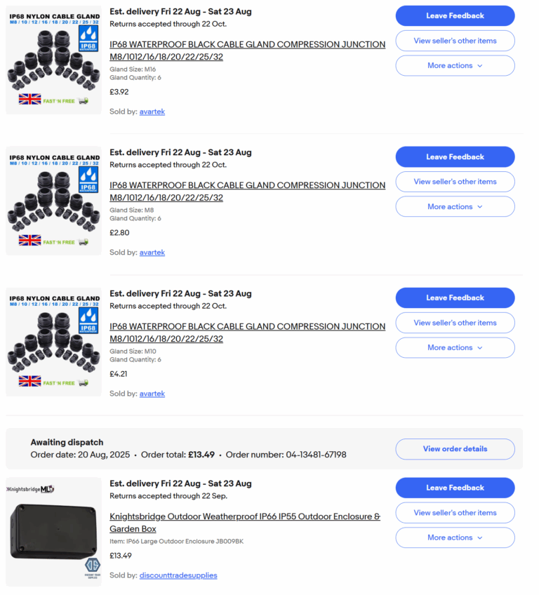
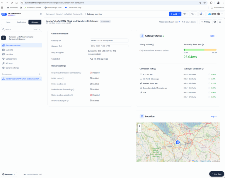
Very busy at work but I’ve still been doing a lot. Got the new Gateway set up and tested. Looks like we have our connectivity. Been spending money today ordering parts for the next stage: Enclosure, glands, anemometer, weather vane. Still deciding whether to go with a 12V battery or Li-Ion cells which will affect my choice of Solar Panel. I have also added a cost table at the bottom of this page.
I have ordered the more expensive gateway that will be sure to work; with support from the Raspberry Pi
ecosystem. I’ll probably put the cheaper gateway on the back burner for now and get it set up sometime in the
future to benefit LoRa users in the black spot near my home. The 1303 will almost certainly work right out of
the box with a pre-setup script.
PM Update: I have spent all evening and night again working on the cheaper gateway and it works! 3am 🤔 Now
I’ve spent £100 of my own cash I didn’t need to but at least it will benefit the community and
be there for future projects I guess.
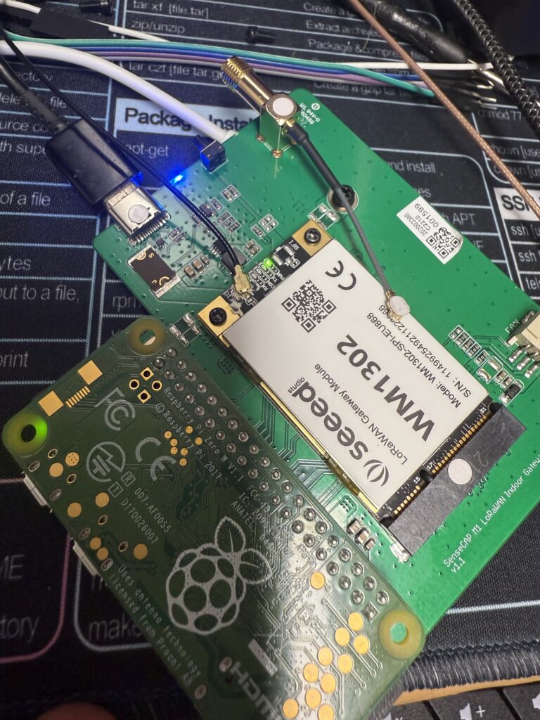
WM1302 gateway arrived from Amazon today. I struggled all day long to try and get this to work. Not mentioned on the listing I discovered it is part of a Helium network mining unit which has been marooned by the system becoming more proprietary and excluding their older hardware from the network. The original unit would have come inside a bigger box and been included with a Raspberry Pi 4b computer which would have been locked tightly onto the Helium network with their own special closed-source software. The ‘gateway’ they sold was just an interface board from the GPIO port to a mini-PCI express and the 1302 transceiver card and because it’s not a commercially available product; there’s not many tinkerers who have used them before which would have made this an easy job.
After spending the whole day and night just about managing to get the RX and TX lights blinking – by 0230 I had to get some sleep for work in the morning. The standing problem is that I can talk to the control module; but I couldn’t get the two transceiver chips to wake up and work. There’s a reset signal and there’s an enable signal – you have to know exactly what to do with these signals to get the transceivers to function or they just shut down.
I made some progress by installing a different software package that does get the transceivers working but I need to decompile this installation to be able to find out exactly how it operates them… not an easy task.
Day off – Over the drink/develop limit *hic* 🥴😆
Jon & I did a flight test of the LoRa scanner today. JESUS CHRIST, the range is phenomenally good from the air! Flying out of Blackpool over Southport area heading down the Low Level Corridor it looks like it has reached all the way to Colwyn Bay; roughly 53km!!!
Been testing the LoRa scanner I have set up: at work travelling to Cheltenham and Devon. Seems
to work a charm. I have the server app working great too. The captured data can be seen at
https://ttn.supergalley.com that will be used to show the
weather data on the Chirk airfield website.
on the downside: the LoRa gateway that I was hoping to use at Chirk seemed to be offline today as I
drove past. I hope this is an anomaly and at there is another one working at the Airfield. Failing that
we can probably set up a gateway at Chirk so it never goes down. Here is the C++ code created for the LoRa Scanner:
  /* Heltec WiFi LoRa 32 V3 (ESP32-S3 + SX1262)
   OLED always-on, GPS (UART1 on GPIO1/2), and robust LoRaWAN join/send
   - EU868 / OTAA / FPort 2 / ~30 s
   - OLED initialised ONCE; never re-inited; Vext never toggled after boot
   - Page flip every 3 s (GPS / LoRa+System), 2 Hz draw
   - PRG button: first press freezes auto-cycle; next presses toggle page
   - Join watchdog: re-init if still not joined after 180 s
   - Auto pixel-invert for 120 s after a successful uplink
   - OLED keepalive + lowPowerHandler override so the screen never naps
*/
#include <Arduino.h>
#include <Wire.h>
#include "HT_SSD1306Wire.h"   // Heltec’s SSD1306 OLED driver
#include "HT_TinyGPS++.h"     // Lightweight GPS parser
#include "LoRaWan_APP.h"      // Heltec LoRaWAN state machine
#include <limits.h>           // for ULONG_MAX
// -----------------------------
//        PMU (AXP2101)
// -----------------------------
// The Heltec V3 board uses an AXP2101 PMU. Some revisions map it at 0x34,
// others at 0x35. We probe both. We only use it to read battery voltage.
//
// Relevant registers (datasheet naming):
//  - BAT_VOL_H/L: 12-bit battery voltage ADC result
//  - ADC_EN1: enables VBAT/VBUS ADC channels
static uint8_t PMU_ADDR = 0x34;
#define AXP2101_BAT_VOL_H 0x78
#define AXP2101_BAT_VOL_L 0x79
#define AXP2101_ADC_EN1   0x58  // enable bits for ADC channels

// ---- minimal I2C helpers ----
static bool i2cWrite8(uint8_t addr, uint8_t reg, uint8_t val) {
  Wire.beginTransmission(addr);
  Wire.write(reg);
  Wire.write(val);
  return Wire.endTransmission() == 0;
}
static bool i2cRead8(uint8_t addr, uint8_t reg, uint8_t &val) {
  Wire.beginTransmission(addr);
  Wire.write(reg);
  if (Wire.endTransmission(false) != 0) return false;          // keep bus active
  if (Wire.requestFrom(addr, (uint8_t)1) != 1) return false;    // read 1 byte
  val = Wire.read();
  return true;
}
// Try 0x34 then 0x35. If neither ACKs, we skip battery features.
static bool pmuProbe() {
  Wire.beginTransmission(0x34);
  if (Wire.endTransmission() == 0) { PMU_ADDR = 0x34; return true; }
  Wire.beginTransmission(0x35);
  if (Wire.endTransmission() == 0) { PMU_ADDR = 0x35; return true; }
  return false;
}
// Flip on ADC channels for VBAT/VBUS so reads return real numbers.
static bool axpEnableAdcBatt() {
  uint8_t v = 0;
  if (!i2cRead8(PMU_ADDR, AXP2101_ADC_EN1, v)) return false;
  v |= (1 << 7); // BAT_VOLT_EN (bit position per typical AXP2101 map)
  v |= (1 << 5); // VBUS_VOLT_EN
  return i2cWrite8(PMU_ADDR, AXP2101_ADC_EN1, v);
}
// Read 12-bit battery voltage. Datasheet scale: 1 LSB = 1.1 mV.
static float readBatteryVoltageAXP2101() {
  Wire.beginTransmission(PMU_ADDR);
  Wire.write(AXP2101_BAT_VOL_H);
  if (Wire.endTransmission(false) != 0) return 0.0f;           // restart
  if (Wire.requestFrom(PMU_ADDR, (uint8_t)2) != 2) return 0.0f;
  uint8_t hi = Wire.read();
  uint8_t lo = Wire.read();
  uint16_t raw = ((uint16_t)hi << 4) | (lo >> 4);               // pack 12 bits
  return (raw * 1.1f) / 1000.0f;                                // volts
}
// -----------------------------
//            OLED
// -----------------------------
// Heltec wires the OLED to SDA_OLED/SCL_OLED and powers it from Vext.
// On this board: Vext LOW = enabled, HIGH = disabled.
static SSD1306Wire display(0x3c, 400000, SDA_OLED, SCL_OLED,
                           GEOMETRY_128_64, RST_OLED);
static inline void VextON()  { pinMode(Vext, OUTPUT); digitalWrite(Vext, LOW);  }
static inline void VextOFF() { pinMode(Vext, OUTPUT); digitalWrite(Vext, HIGH); }
static bool oledInverted = false;   // track invert state for minimal I2C chatter
static uint32_t lastOledKA = 0;     // last OLED keepalive tick
// Change pixel polarity only when state actually changes.
static inline void oledSetInversion(bool inv) {
  if (inv == oledInverted) return;
  oledInverted = inv;
  if (inv) display.invertDisplay(); else display.normalDisplay();
}
// Initialise the OLED once at boot and never re-initialize again.
// Re-initting OLEDs mid-flight leads to flicker and bus glitches.
static void oledInitOnce() {
  VextON();                                // power the display rail
  delay(2);
  Wire.begin(SDA_OLED, SCL_OLED, 400000);  // fast I2C for snappier draws
  display.init();
  display.setTextAlignment(TEXT_ALIGN_LEFT);
  display.setFont(ArialMT_Plain_10);
  display.displayOn();                     // ensure panel is awake
  oledSetInversion(false);
  display.clear();
  display.drawString(0,0,"OLED ready");
  display.drawString(0,12,"Init GPS @115200 (RX1=GPIO1 TX1=GPIO2)");
  display.drawString(0,24,"Init LoRaWAN EU868 OTAA…");
  display.display();
}
// Keep the OLED rail alive and poke the controller once a second so
// firmware “sleep” hooks don’t blank the panel.
static inline void oledKeepAlive() {
  pinMode(Vext, OUTPUT);
  digitalWrite(Vext, LOW);                 // rail on
  uint32_t now = millis();
  if (now - lastOledKA >= 1000) {
    display.displayOn();                   // sends 0xAF wake
    lastOledKA = now;
  }
}
// Convenience draw with 5 lines at 12 px spacing.
static void oledDraw(const String &l0, const String &l1="",
                     const String &l2="", const String &l3="",
                     const String &l4="") {
  display.clear();
  if (l0.length()) display.drawString(0,  0, l0);
  if (l1.length()) display.drawString(0, 12, l1);
  if (l2.length()) display.drawString(0, 24, l2);
  if (l3.length()) display.drawString(0, 36, l3);
  if (l4.length()) display.drawString(0, 48, l4);
  display.display();
  display.displayOn();                     // extra nudge to stay awake
}
// -----------------------------
//        LoRaWAN (OTAA)
// -----------------------------
// All keys are MSB order as expected by Heltec’s wrapper.
// appEui often left zero for TTN v3 console-created devices.
uint8_t appEui[] = { 0x00,0x00,0x00,0x00,0x00,0x00,0x00,0x00 };
uint8_t devEui[] = { 0x9A,0x84,0x81,0xB0,0x00,0x00,0xEC,0x87 };
uint8_t appKey[] = { 0xE5,0xD8,0x35,0xA7,0x9E,0x80,0x89,0xED,0xC3,0x73,0xF1,0x06,0xF6,0x62,0x4C,0xAC };
// Library expects these even with OTAA; they’re ignored until join success.
uint16_t userChannelsMask[6] = { 0x00FF, 0x0000, 0x0000, 0x0000, 0x0000, 0x0000 };
uint8_t  nwkSKey[16] = {0};
uint8_t  appSKey[16] = {0};
uint32_t devAddr     = 0;
// Region and behavior knobs
LoRaMacRegion_t loraWanRegion = LORAMAC_REGION_EU868;
DeviceClass_t   loraWanClass  = CLASS_A;
bool  overTheAirActivation    = true;     // OTAA
bool  loraWanAdr              = true;     // let network tune DR
bool  isTxConfirmed           = false;    // unconfirmed uplinks
uint8_t  appPort              = 2;        // TTNMapper default
uint8_t  confirmedNbTrials    = 1;        // unused (unconfirmed)
uint32_t appTxDutyCycle       = 30000;    // 30 s between frames (plus jitter)
// Track the DR we set; Heltec wrapper doesn’t expose a getter.
static int8_t currentDR = 2; // EU868 DR2 ≈ SF10/125
// -----------------------------
//             GPS
// -----------------------------
// GPS is wired to UART1 on GPIO1/2. TinyGPS++ ingests raw NMEA and gives
// parsed fields with validity bits and “age” timing.
TinyGPSPlus GPS;
static const uint32_t GPS_BAUD = 115200;
static const int GPS_RX = 1;   // ESP32 pin receiving data from GPS TX
static const int GPS_TX = 2;   // ESP32 pin to GPS RX (rarely used)
static uint32_t lastCharCount=0, lastCharTick=0;
static uint16_t bytesPerSec=0; // rough NMEA throughput for debugging
// Feed TinyGPS++ from Serial1 for up to max_ms. Also compute bytes/sec.
static inline void feedGPS(uint32_t max_ms = 5) {
  uint32_t start = millis();
  while (Serial1.available() && (millis()-start) < max_ms) {
    GPS.encode((char)Serial1.read());
  }
  if (millis() - lastCharTick >= 1000) {
    uint32_t cur = GPS.charsProcessed();
    bytesPerSec = (uint16_t)(cur - lastCharCount);
    lastCharCount = cur; lastCharTick = millis();
  }
}
// -----------------------------
//           Battery
// -----------------------------
// Wrap PMU read for the app. If PMU missing, returns 0.00 V.
static float readBatteryV() {
  return readBatteryVoltageAXP2101();
}
// Crude VBAT→% mapping with soft knee. Clamped 3.20–4.18 V -> 0–100 %.
static int batteryPercent(float v) {
  if (v <= 3.20f) return 0;
  if (v >= 4.18f) return 100;
  float x = (v - 3.20f) / (4.18f - 3.20f);
  x = x * (1.1f - 0.1f * x);   // gentle ease curve
  int p = (int)(x * 100.0f + 0.5f);
  if (p < 0) p = 0; if (p > 100) p = 100;
  return p;
}
// -----------------------------
//     State / Telemetry UI
// -----------------------------
static bool     joined        = false;   // latched once first TX happens
static uint32_t joinStartMs   = 0;       // for join watchdog
static uint32_t uplinkCount   = 0;       // total successful sends
static uint32_t lastTxMs      = 0;       // for OLED inversion window
// Page/UI handling
static bool     showGPS       = true;    // which page is visible
static bool     autoCycle     = true;    // auto-toggle every 3 s
static uint32_t nextFlip      = 0;
static uint32_t nextFrame     = 0;       // 2 Hz drawing cadence
static const uint32_t FRAME_MS = 500;
static const uint32_t JOIN_WATCHDOG_MS = 180000; // re-init if join stalls
static const uint32_t INVERT_MS        = 120000; // invert after TX
// PRG button is on GPIO0 and pulled up when idle.
static const int PIN_PRG = 0;
static bool lastBtn = true;              // HIGH = idle
static uint32_t lastBtnMs = 0;
static const uint16_t DEBOUNCE_MS = 150;
// -----------------------------
//          Uplink payload
// -----------------------------
// Heltec wrapper uses global appData/appDataSize for send buffer.
extern uint8_t appData[];
extern uint8_t appDataSize;
// TTNMapper expects 12 bytes: lat(4) lon(4) alt(2) hdop*10(1) sats(1).
static void prepareTxFrame(uint8_t /*port*/) {
  int32_t lat = 0, lon = 0; int16_t alt = 0; uint8_t hd=255, sats=0;
  bool hasFix = GPS.location.isValid();
  if (hasFix) { lat = (int32_t)(GPS.location.lat()*1e7); lon = (int32_t)(GPS.location.lng()*1e7); }
  if (GPS.altitude.isValid())   alt  = (int16_t)GPS.altitude.meters();
  if (GPS.hdop.isValid())       hd   = (uint8_t)min(255.0, GPS.hdop.hdop()*10.0);
  if (GPS.satellites.isValid()) sats = (uint8_t)GPS.satellites.value();
  uint8_t p[12]; int i=0;
  p[i++]=(lat>>24)&0xFF; p[i++]=(lat>>16)&0xFF; p[i++]=(lat>>8)&0xFF; p[i++]=lat&0xFF;
  p[i++]=(lon>>24)&0xFF; p[i++]=(lon>>16)&0xFF; p[i++]=(lon>>8)&0xFF; p[i++]=lon&0xFF;
  p[i++]=(alt>>8)&0xFF;  p[i++]=alt&0xFF;      p[i++]=hd;            p[i++]=sats;
  memcpy(appData, p, sizeof(p)); appDataSize = sizeof(p); appPort = 2;
}
// -----------------------------
//           Pages
// -----------------------------
static void drawGpsPage() {
  bool hasFix = GPS.location.isValid();
  uint8_t sats = GPS.satellites.isValid()? GPS.satellites.value():0;
  float hdop = GPS.hdop.isValid()? GPS.hdop.hdop():NAN;
  uint32_t age = GPS.location.age();  // ms, or ULONG_MAX if invalid
  String l0 = hasFix ? "GPS: FIX" : "GPS: searching…";
  if (!autoCycle) l0 += "  [MAN]";
  String l1 = "Sats " + String(sats);
  if (!isnan(hdop)) l1 += "  HDOP " + String(hdop,1);
  String l2, l3, l4;
  if (hasFix) {
    l2 = "Lat " + String(GPS.location.lat(),6);
    l3 = "Lon " + String(GPS.location.lng(),6);
    if (GPS.altitude.isValid()) l4 = "Alt " + String(GPS.altitude.meters(),0) + " m";
    else l4 = "Fix age " + String(age/1000.0,1) + "s";
  } else {
    l2 = "NMEA " + String(bytesPerSec) + " B/s";
    l3 = (age==ULONG_MAX) ? "Fix age ?" : ("Fix age " + String(age/1000.0,1) + "s");
    l4 = "Waiting for sky view…";
  }
  oledDraw(l0,l1,l2,l3,l4);
}
static void drawLoRaPage() {
  String l0 = joined ? "LoRa: JOINED" : "LoRa: joining…";
  l0 += "  DR"; l0 += String(currentDR);
  l0 += loraWanAdr ? " ADR:on" : " ADR:off";
  if (!autoCycle) l0 += "  [MAN]";
  String l1 = "Uplink Count: " + String(uplinkCount);
  if (lastTxMs) l1 += "  TX " + String((millis()-lastTxMs)/1000) + "s ago";
  if (deviceState==DEVICE_STATE_CYCLE) {
    uint32_t eta = (txDutyCycleTime>millis()) ? ((txDutyCycleTime - millis())/1000) : 0;
    l1 += "  next " + String(eta) + "s";
  }
  float vb = readBatteryV();
  int pc = batteryPercent(vb);
  String l2;
  if (vb < 2.5f) l2 = "Batt USB-only   0%";  // PMU not reporting
  else           l2 = "Batt " + String(vb,2) + "V  " + String(pc) + "%";
  String l3 = "EU868  FP:" + String(appPort) + "  duty~" + String(appTxDutyCycle/1000) + "s";
  String l4 = "PRG: freeze/toggle pages";
  oledDraw(l0,l1,l2,l3,l4);
}
// -----------------------------
//        Button handling
// -----------------------------
// Single button: first press freezes auto-cycle; subsequent presses toggle pages.
static void handleButton() {
  bool now = digitalRead(PIN_PRG); // HIGH idle, LOW pressed
  uint32_t t = millis();
  if (now != lastBtn && (t - lastBtnMs) > DEBOUNCE_MS) {
    lastBtnMs = t;
    if (now == LOW) {
      if (autoCycle) autoCycle = false;
      else           showGPS = !showGPS;
    }
    lastBtn = now;
  }
}
// -----------------------------
//   Low-power hook override
// -----------------------------
// Heltec’s LoRaWAN state machine idles via sleep calls. We override the
// weak lowPowerHandler() so the OLED rail never naps while LoRa waits.
extern "C" void lowPowerHandler(void) {
  oledKeepAlive();   // keep rail high and panel awake
  delay(1);          // tiny yield
}
// -----------------------------
//        setup() / loop()
// -----------------------------
void setup() {
  Serial.begin(115200);
  delay(100);
  pinMode(PIN_PRG, INPUT_PULLUP);
  oledInitOnce();                 // powers and configures OLED, starts I2C
  // GPS on UART1. We rarely transmit to the GPS but wire TX in case.
  Serial1.begin(GPS_BAUD, SERIAL_8N1, GPS_RX, GPS_TX);
  lastCharTick = millis(); lastCharCount = GPS.charsProcessed();
  // Heltec board init. Note their macro typo: SLOW_CLK_TPYE…
  Mcu.begin(HELTEC_BOARD, SLOW_CLK_TPYE);
  // LoRa defaults and UI timers
  currentDR = 2;                  // DR2 EU868
  nextFlip  = millis() + 3000;    // first auto flip in 3 s
  nextFrame = millis() + FRAME_MS;

  // PMU bring-up: optional. If probing fails we still operate.
  if (!pmuProbe()) {
    Serial.println("PMU not found at 0x34/0x35; VBAT will read 0.00V");
  } else {
    if (!axpEnableAdcBatt()) {
      Serial.println("PMU found but ADC enable failed; VBAT may be 0.00V");
    } else {
      Serial.printf("PMU on 0x%02X, ADC enabled.\n", PMU_ADDR);
    }
  }
}
void loop() {
  // Keep OLED alive first each tick so any later sleeps don't blank it.
  oledKeepAlive();
  feedGPS(8);              // parse up to ~8 ms of NMEA this iteration
  handleButton();          // debounce and act on PRG presses
  // Invert display for a visual “TX success” window.
  bool recentTx = (lastTxMs != 0) && ((millis() - lastTxMs) <= INVERT_MS);
  oledSetInversion(recentTx);
  // Auto flip page every 3 s while autoCycle is true.
  if (autoCycle && millis() >= nextFlip) {
    showGPS = !showGPS;
    nextFlip = millis() + 3000;
  }
  // Draw UI at 2 Hz regardless of LoRa state machine.
  if (millis() >= nextFrame) {
    if (showGPS) drawGpsPage(); else drawLoRaPage();
    nextFrame += FRAME_MS;
  }
  // -------------------------
  // LoRaWAN state machine
  // -------------------------
  switch (deviceState) {
    case DEVICE_STATE_INIT:
      // Configure radio and set starting data rate
      LoRaWAN.init(loraWanClass, loraWanRegion);
      LoRaWAN.setDefaultDR(currentDR);
      joinStartMs = millis();
      deviceState = DEVICE_STATE_JOIN;
      break;
    case DEVICE_STATE_JOIN:
      // Attempt OTAA join. Library handles retries.
      LoRaWAN.join();
      // If we’ve been trying for > 3 minutes, re-init radio and try again.
      if (!joined && (millis() - joinStartMs) > JOIN_WATCHDOG_MS) {
        LoRaWAN.init(loraWanClass, loraWanRegion);
        LoRaWAN.setDefaultDR(currentDR);
        joinStartMs = millis();
      }
      break;
    case DEVICE_STATE_SEND:
      // We only get here when the wrapper says it’s time to send.
      if (!joined) joined = true;           // latch first TX as "joined"
      prepareTxFrame(appPort);              // fill appData/appDataSize
      LoRaWAN.send();                       // unconfirmed uplink
      uplinkCount++;
      lastTxMs = millis();                  // start OLED invert window
      deviceState = DEVICE_STATE_CYCLE;     // schedule next send
      break;
    case DEVICE_STATE_CYCLE:
      // Add random jitter to avoid gateway sync collisions.
      txDutyCycleTime = appTxDutyCycle +
                        randr(-APP_TX_DUTYCYCLE_RND, APP_TX_DUTYCYCLE_RND);
      LoRaWAN.cycle(txDutyCycleTime);       // tell wrapper when to wake for SEND
      deviceState = DEVICE_STATE_SLEEP;     // fall into sleep handler
      break;
    case DEVICE_STATE_SLEEP:
      // Wrapper will idle the MCU; our lowPowerHandler keeps OLED alive.
      LoRaWAN.sleep(loraWanClass);
      break;
    default:
      // Safety net: reboot state machine.
      deviceState = DEVICE_STATE_INIT;
      break;
  }
}
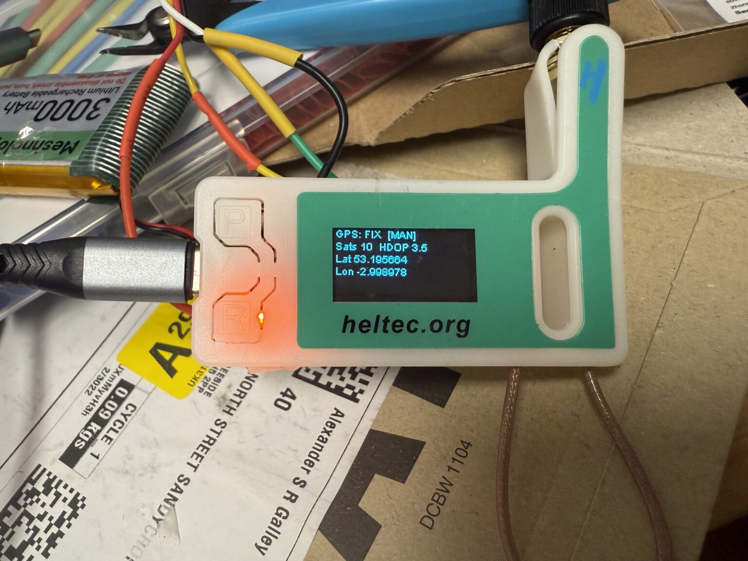
EUREEKA!!! The new GPS unit arrived today and has been coded into the ESP32 board. Finally, upon power-on
– it very quickly got a lock on about 20 satellites.
Because I live in a massive LoRa gateway black hole; I have decided to buy a LoRa gateway to set up at my house.
This will do the people of Chester area a massive favour but this is completely unrelated to the Weather Station
project; it’s just paying forward the favour from the nice person who has set up a gateway up the road from Chirk
which hopefully we will be using to stream our weather data when the project is finished and ready for testing.
I live next to EGNR – Hawarden Airport and as you can see there’s nothing for miles; which will cause problems when I’m building and testing the weather sensors, software and processing hardware. I will likely be a bit quiet for the next three days as I’m being sent down to Devon for work. Have a great week!
MASSIVE Thankyou to Al and Stu who have very kindly started off the GoFundMe for this weather station. We are extremely grateful for your help towards this excellent community project. Obviously I am sharing my progress regularly on this page but if anyone would like to offer advice, requests or share their knowledge and experience you can email me on supergalley.
Today I did some work diagnosing the GPS problem. It turns out that the GPS module is a duff: it should have a flashing light on the PCB and use 60mA when working. It was actually causing a Volt-drop on the power terminals to about 1-2V so clearly sucking a lot more power than normal. When measured from a bench PSU it was seen to be drawing 200mA; nearly three times as much as it should.
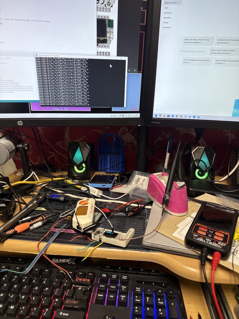
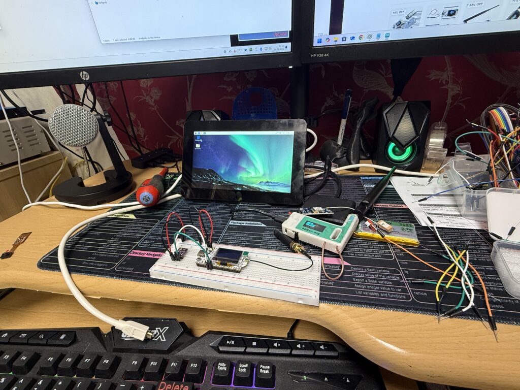
This is where my desk got REALLY messy! I connected my Flipper Zero to my Windows PC as a Com Port and created a
PowerShell script to ‘spoof’ the GPS coordinates of my house and send it a made up number of satellites every few
seconds. I then set up the Flipper Zero as a USB to UART bridge and connected two wires; one to Ground and the other
to Pin13 (TX) so that this wire would be exactly the same as the signal that the GPS board should be sending to the
LoRa transceiver. It wouldn’t work on the RX pin so after changing Pin1 to listen for UART instead, the LoRa OLED
display suddenly started receiving the GPS coordinates and a random number of satellites every few seconds 🥳🥳🥳
Diagnosis: the RX pin is burnt out AND the faulty GPS module was the murderer!!!
New GPS module ordered from ThePiHut should be with me tomorrow. Also I realised that the antenna that came with the
LoRa board is meant for 915MHz and not 868MHz that we use in the UK so replacement matching antenna ordered.
The Heltec ESP32 V3 LoRa board turned up from Amazon along with the GPS module today. After hours and hours of creating Arduino code and registering the device with the TTN network I left for the airfield. I could never get a GPS lock at all, but as I got near Wrexham the LoRa finally connected and the little OLED display reported that a packet had been sent… EUREEKA!!!
Walking all over the airfield it was happily sending a packet to the local gateway every thirty seconds. This means we can use LoRa to send our weather data to the Internet, free of charge, FOREVER!!! 🥳🥳🥳 GPS still never connected 😒
OK, the first thing I need to do is to assess the best method of connection to the Internet. I can either use a radio device called a LoRa which can transmit and receive tiny amounts of data quite a long distance with no license needed OR I can buy a Cellular board which will connect to a mobile phone network like EE, Vodafone, O2 or Three and send the data; at a cost £££.
With LoRa there are sometimes stations around and about that will interact with your signal and send and receive your data to the Internet which is exactly what we need. This would be the best method because it costs nothing to operate and it’s perfect for the tiny, TINY amounts of data we are sending.
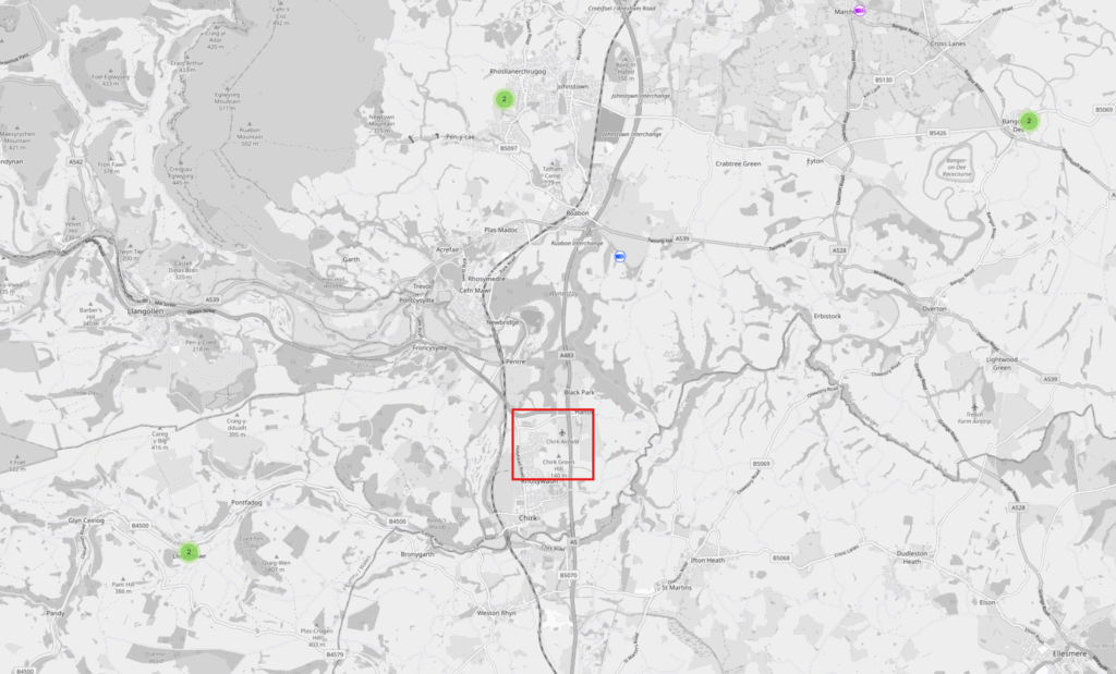
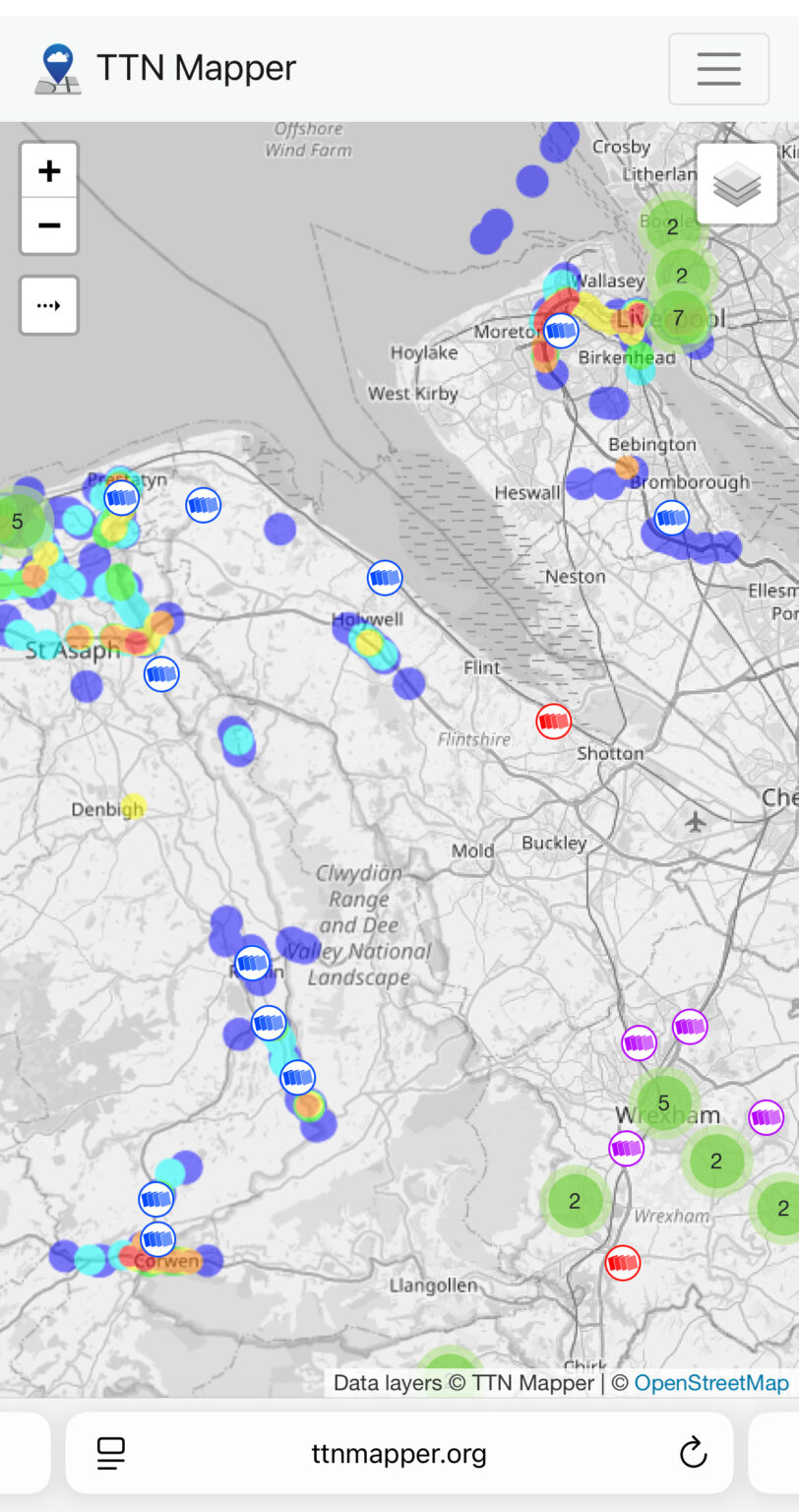
According to TTN (The Things Network) Mapper; there are four stations around Chirk Airfield. The one to the North is a school so they may even be interested in
collaborating with us as they can show their station being used for a greater good!
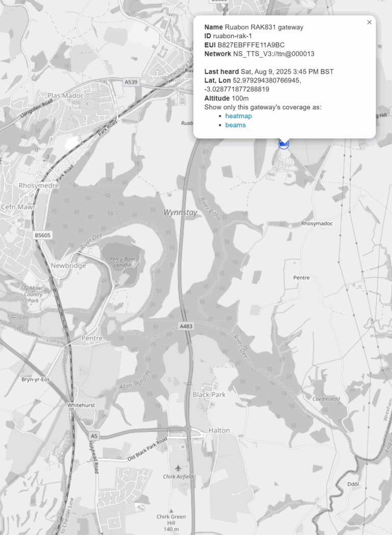
There is a gateway just to the North East. I have ordered a LoRa board which I can use to take to the airfield – hopefully tomorrow and scan for LoRa stations. If lady luck is with us; we will hopefully find a solid connection to the gateway and this will be our connection sorted!

This is the ESP32 LoRa V3 Module Board I have ordered. It comes with a 3 Amp-hour battery which will be ideal in the weather station as it should power it when the light goes and the wind drops for quite a long time. The board also includes the power management to control charging the battery from the 5 Volts input of the USBC port which saves finding and implementing a charging circuit at a later date.
I’m hoping that the Heltec ESP32 module is the same size as the Raspberry Pi Pico I was hoping to use originally as I can use the Pico’s breakout board to make the connections I need to connect the GPS and later, the sensors. Otherwise it’s going to have to go onto a PCB which makes it a bit more permanent and difficult to change.
To do the scanning, I will need a GPS module to add to the LoRa board. How it works is I will flash some firmware I create onto the LoRa board and it will get it’s GPS location and use the LoRa to speak to any stations it finds and that will in turn update the TTNMapper website on the Internet. This both helps out the LoRa community and it will let us know if using the LoRaWAN is a viable option to get our weather data onto the Internet.
Now I have to install the Arduino IDE software because I can’t use my Raspberry Pi programming stuff… oh joy! More to follow…
COSTS:
| Date | Description | Price |
|---|---|---|
| 9/8/2025 | Heltec LoTaWAN ESP32 V3 | £32.99 |
| 9/8/2025 | Buck 5v Regulator | £6.99 |
| 10/8/2025 | U.FL SMA Adapter | £5.49 |
| 10/8/2025 | 868MHz Antennas | £9.99 |
| 15/8/2025 | WM1302 LoRaWAN gateway | £27.84 |
| 17/8/2025 | 868MHz Antenna | £5.90 |
| 17/8/2025 | M5Stack GPS | £9.60 |
| 17/8/2025 | 3v GPS Modules | £10.91 |
| 20/8/2025 | Polycarbonate Enclosure | £13.49 |
| 20/8/2025 | 8mm Glands x6 | £2.80 |
| 20/8/2025 | 10mm Glands x6 | £4.21 |
| 20/8/2025 | 16mm Glands x6 | £3.92 |
| 20/8/2025 | Anemometer and Windvane | £32.49 |